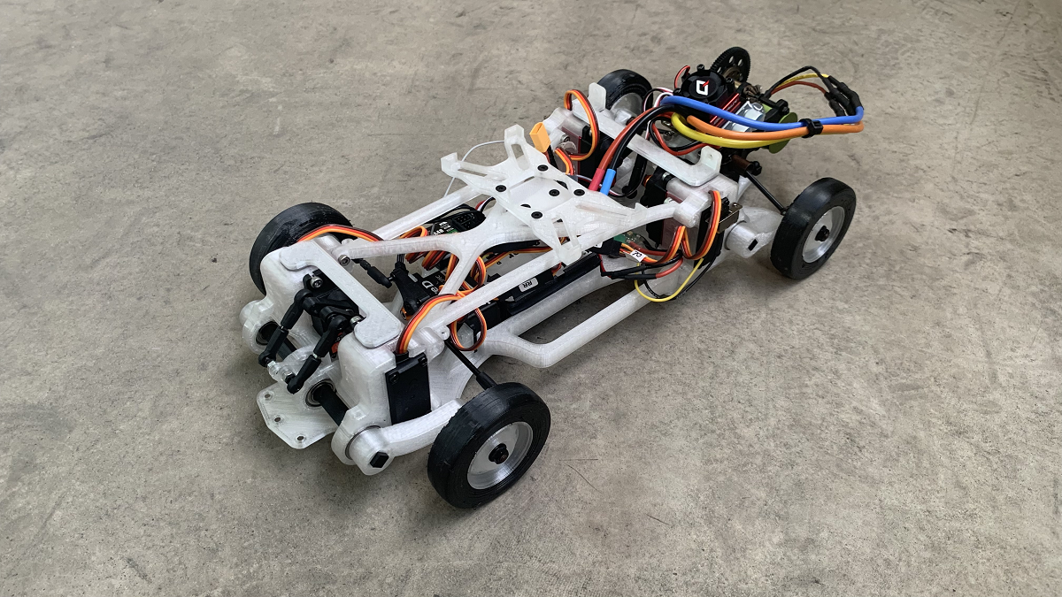
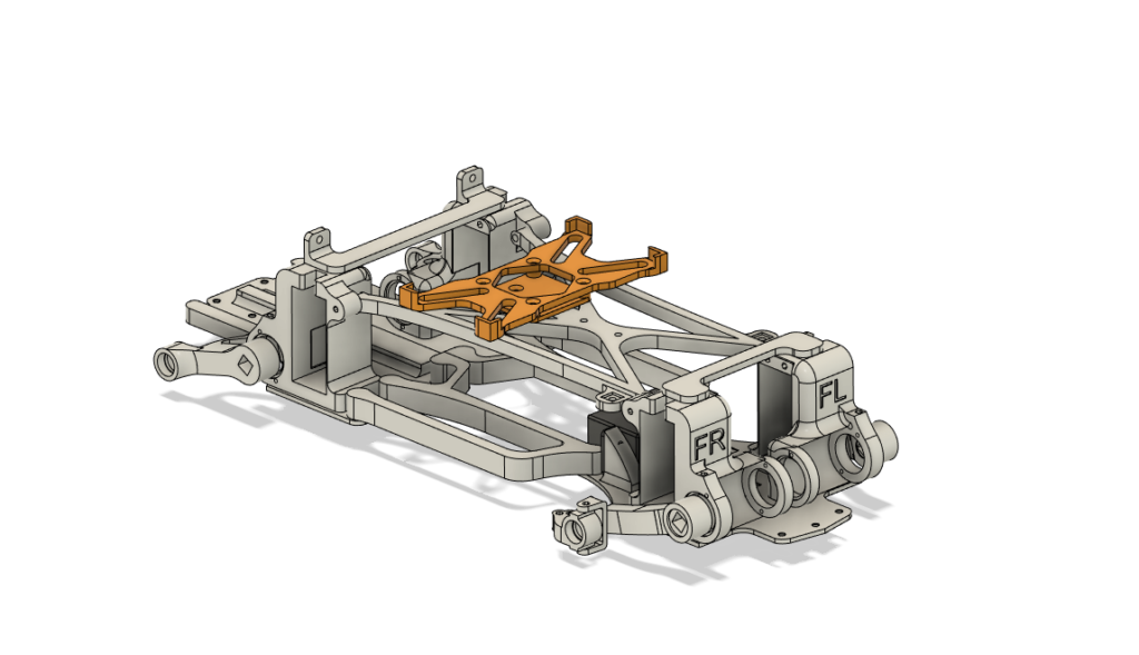
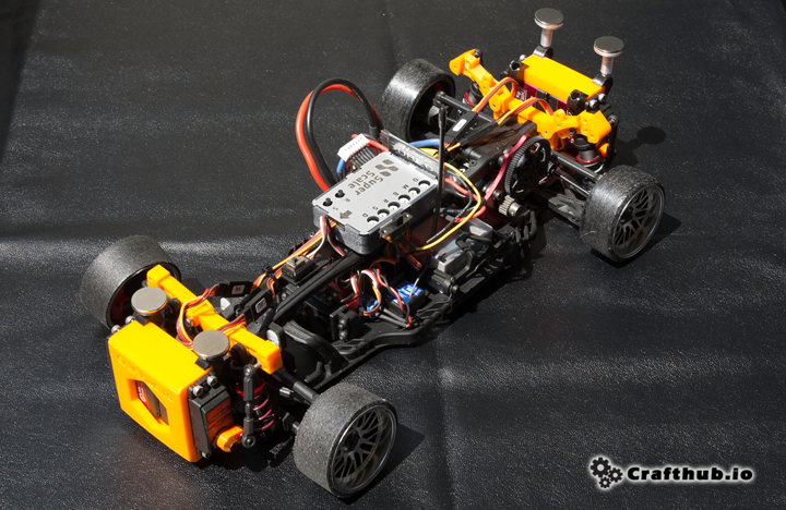
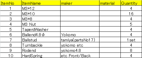
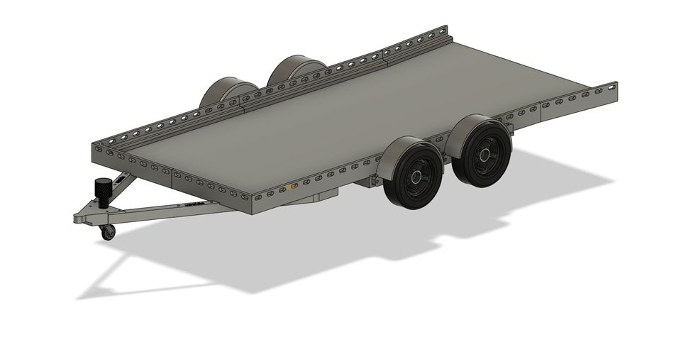
This kit is a chassis to use the Superscale2020 active suspension unit effectively. It features a compact package that combines torsion bars and active suspension in the size of the Tamiya M chassis (wheelbase 239mm).
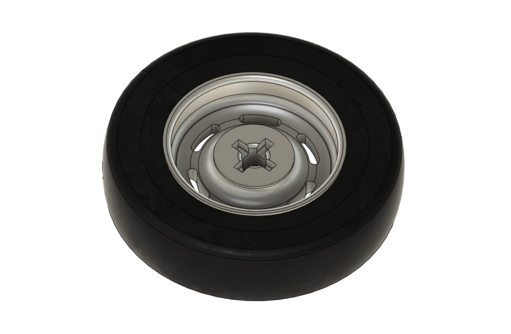
This model also uses gripped tires for a more realistic scale appearance. We recommend using a DC motor for the crawler or a multi-pole brushless DC motor to enjoy realistic behavior at very low speeds.
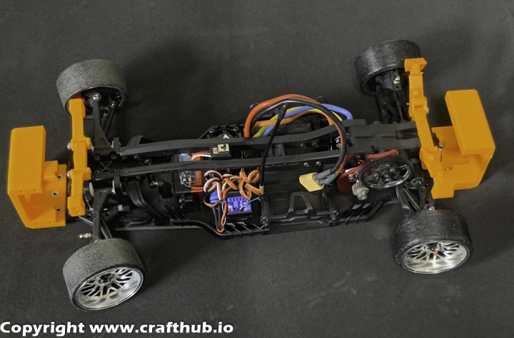
Drivetrain
The drivetrain of this kit is designed to maximize the use of Sakura D5 parts available to everyone. As a result, it is possible to use active suspension at a lower cost than collecting the necessary parts individually.
A steering gyro is not necessarily required, as the tires provide some grip.
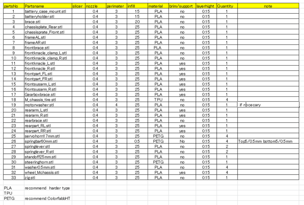
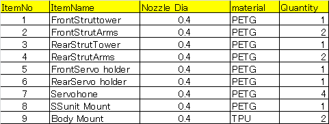
What’s included in the kit
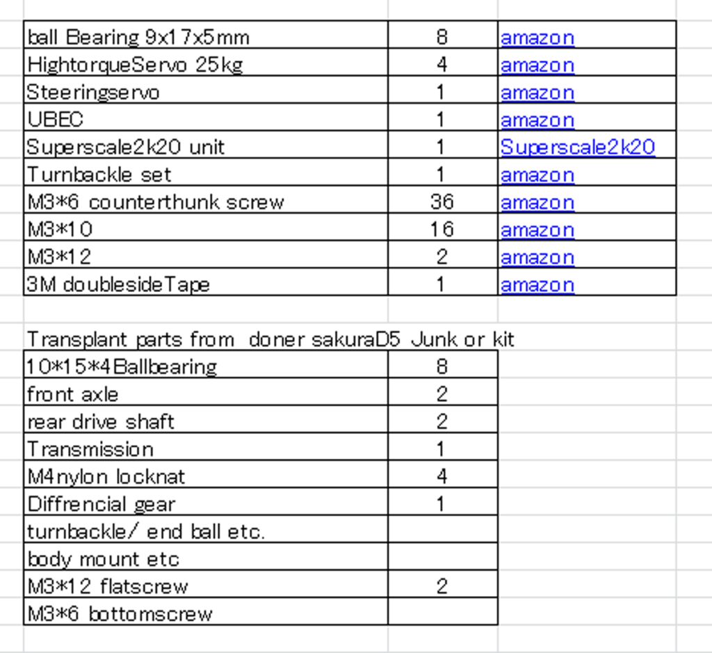
What you need besides the kit
The list with active links can be downloaded from Google drive.
Superscale2020
The Superscale2020 “SS” unit is a key component of this chassis and should be purchased here.
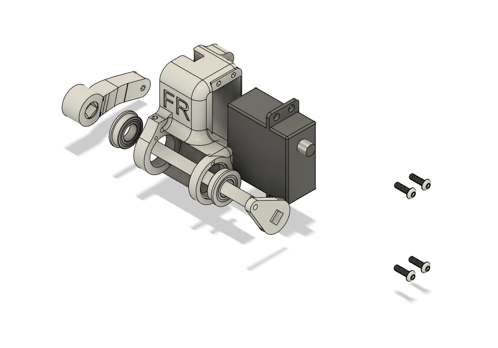
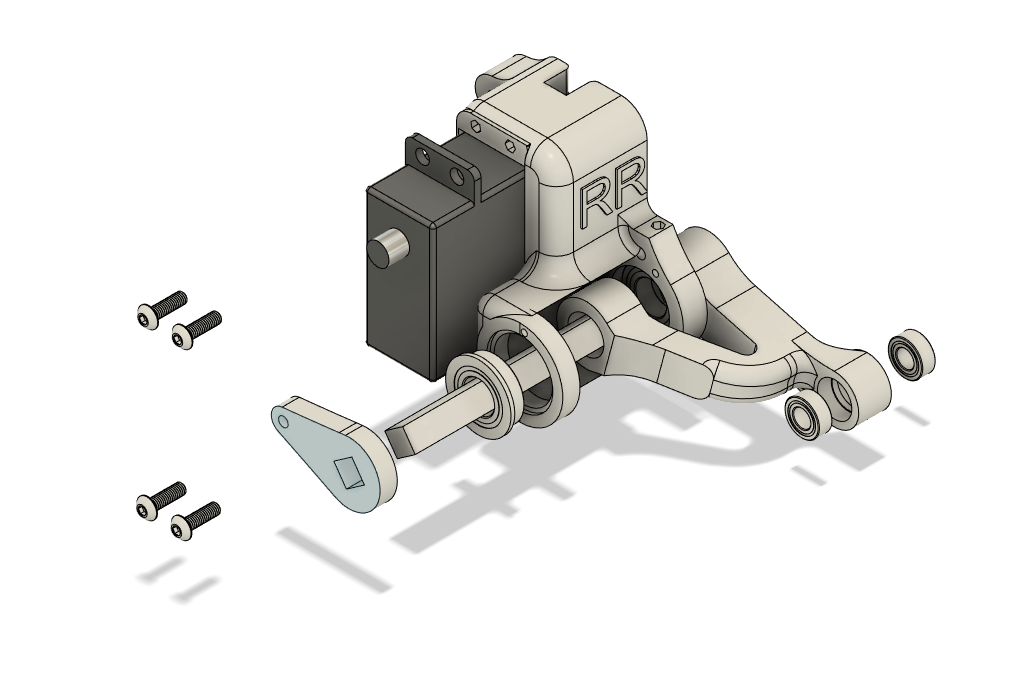
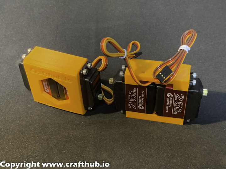
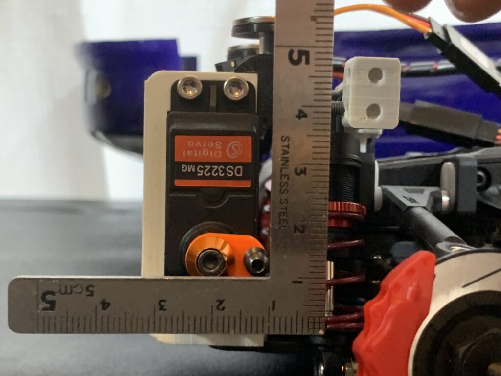
1, Servo and torsion bar box assembly
Front. Install 9*17*5ball bearings and secure servo with M3*10 screws. Do the same for the left side.
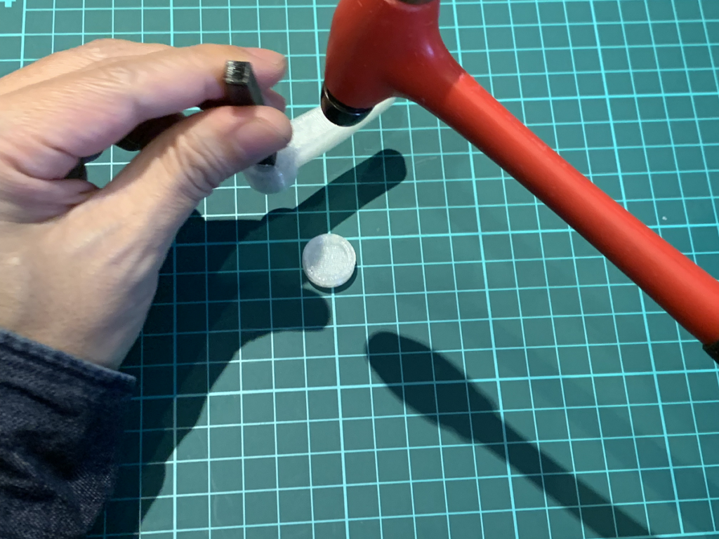
Torsion bars are printed with PETG. Please check the print settings.
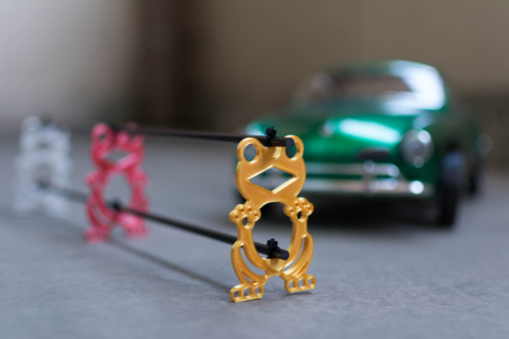
Insert the torsion bar into the suspension arm. Use a rubber hammer or similar tool to gently drive it in; use a Zig to drive in the appropriate amount. Do not install the servo horn at this point.
Install 5*10*4 bearings on the sus arm. fix the servo with M3*10 screw. Do the same for the left side.
Install 9*17*5 bearings and spring bars as for the front side. The spring lever is different from the front side, so be sure to check that it is springlever_R.stl and that the installation orientation matches the diagram.
2,Superscale2k20 “ss”unit Unit initialization
First, use arduinoIDE on your PC to connect to SS unit. Make sure you have the latest version of the firmware. The latest version is Ver1.22 (13 Sep 2022). You can check the version on the serial monitor. Then turn the potentiometer to adjust the offset value to 0, and turn off the power once it is done.
3, Neutral position setting for all servos.
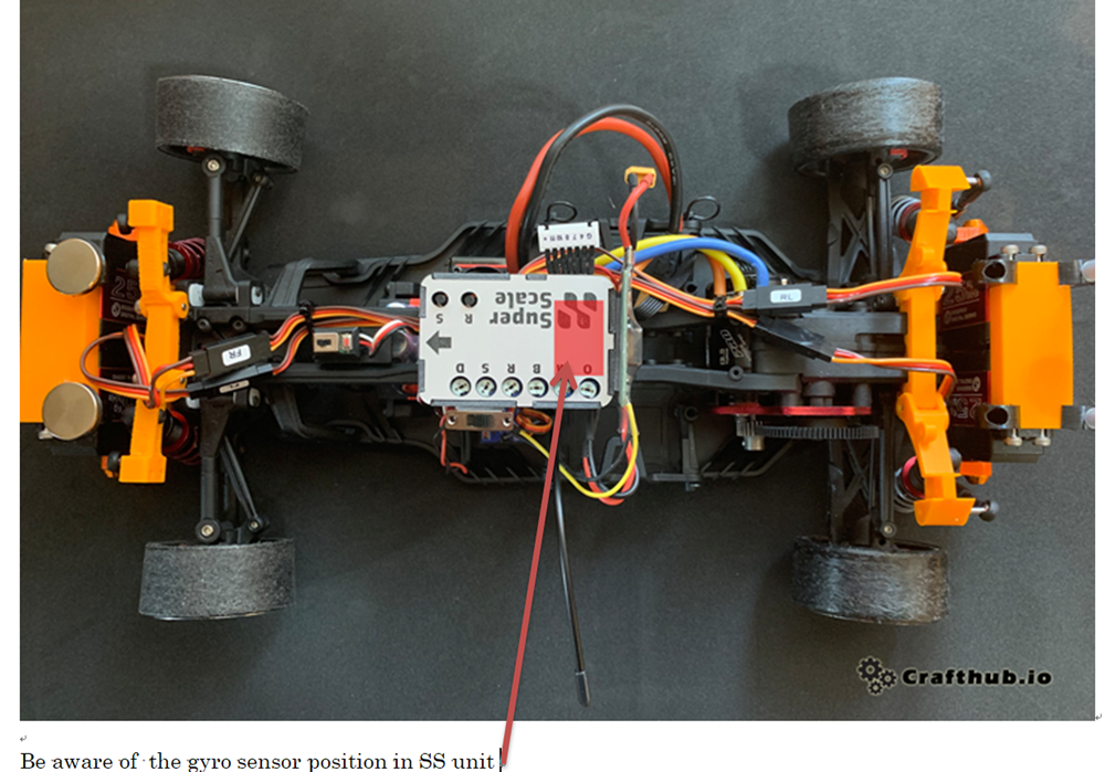
Due to the space limitations of this chassis, it is necessary to connect each servo and SS unit as follows in order to reverse the servo rotation direction.
SSunitRL output>FrontRight servo
SSunitRR output>FrontLeft servo
SSunitFL output >RearRight servo
SSunitFR output >RearLeft servo
After connecting all servos, place the SSunit on a flat surface, turn on the power, and in a few seconds, all servos are in a neutral position and stable. Turn down the power.
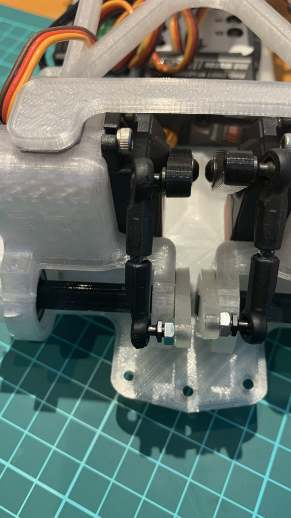
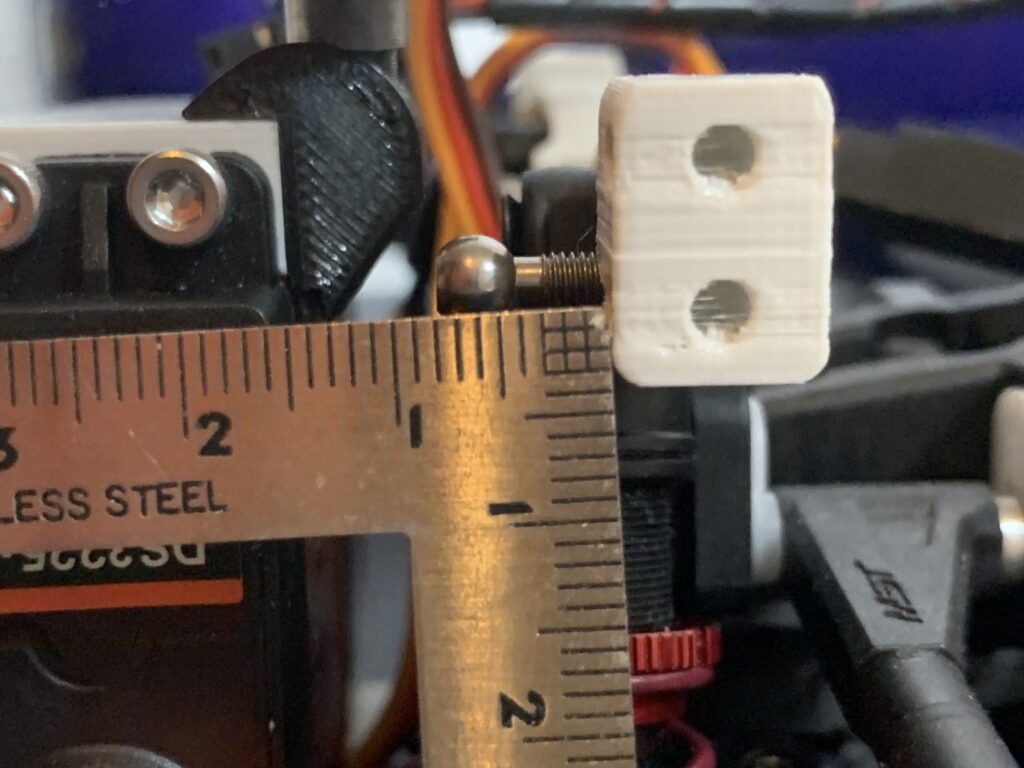
Adjust the neutral position and the axle position with reference to the figure. The servo horn is tightly engaged with the servo output shaft when the screw is tightened.
Set up the left side in the same wayNote the mounting orientation of the ball end!Set up the left side in the same wayNote the mounting orientation of the ball end!
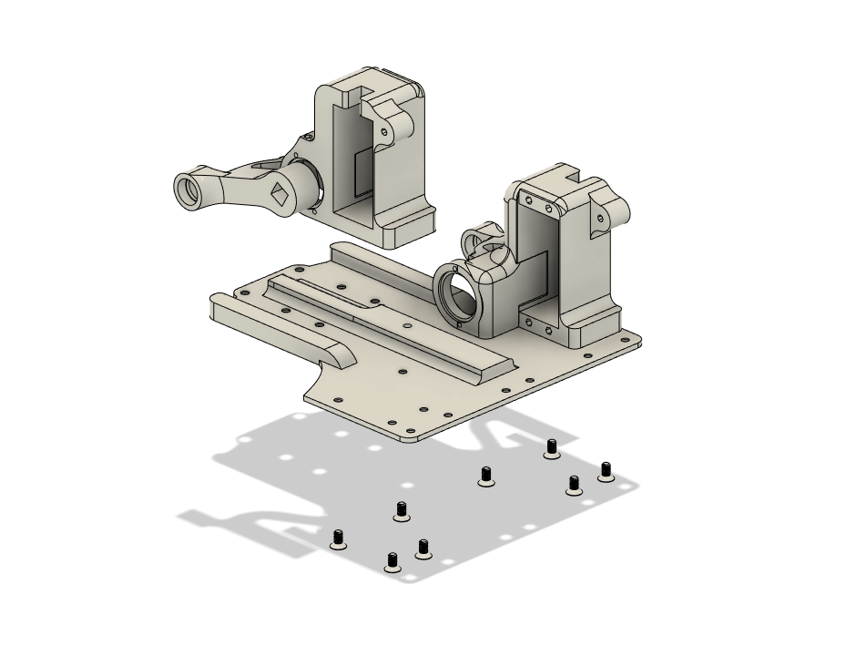
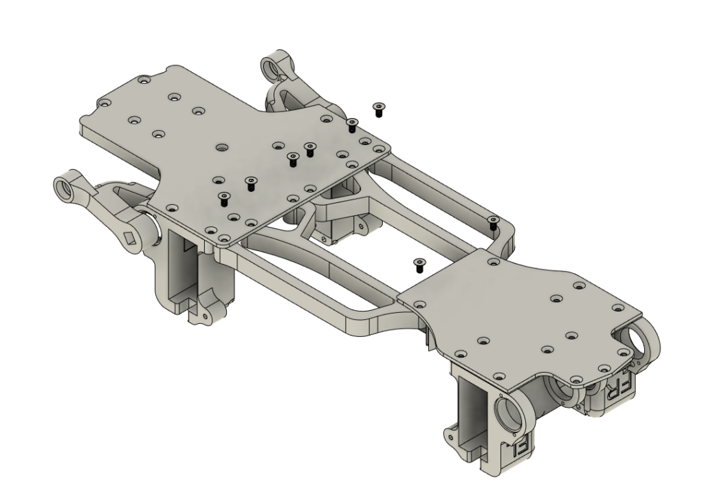
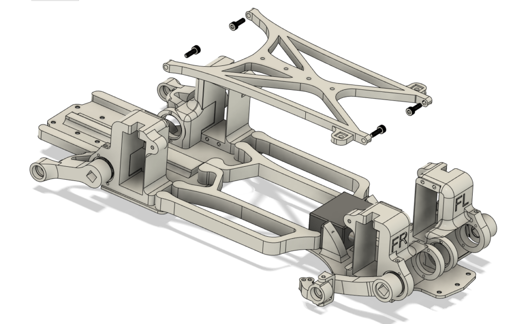
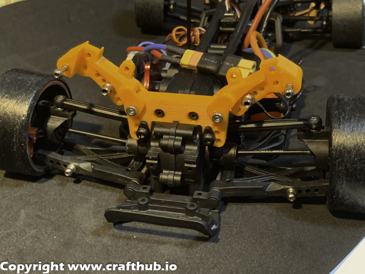
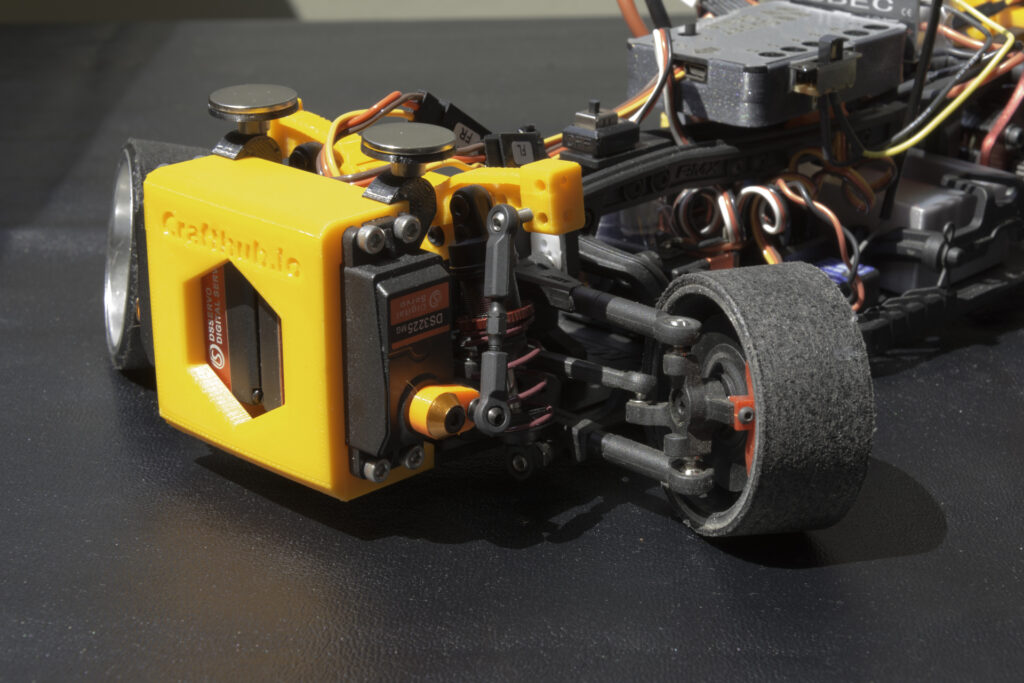
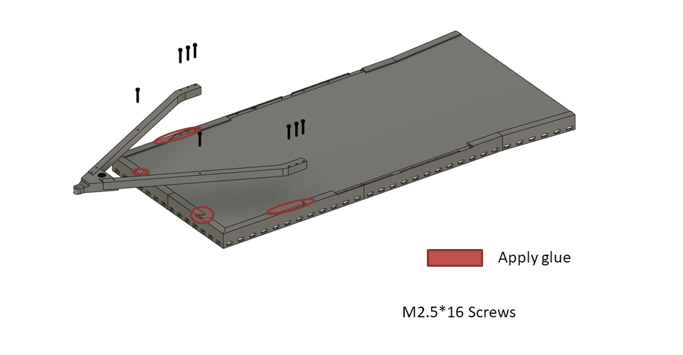
4, Frame Assembly
The steering servo is secured with double side tape.
Then connect the front and rear frames.
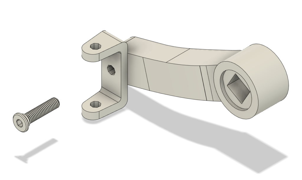
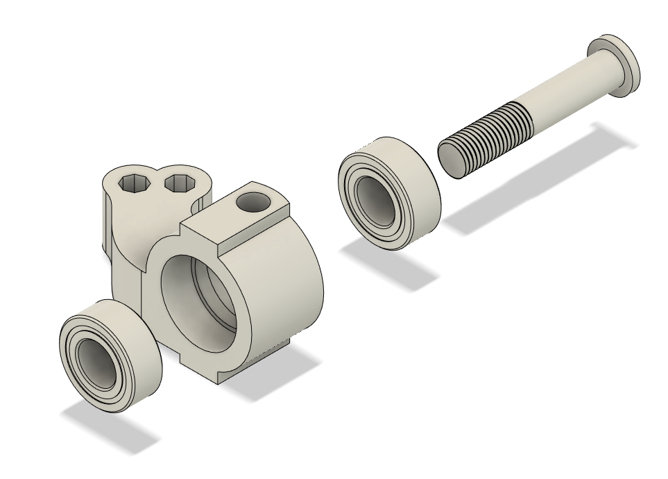
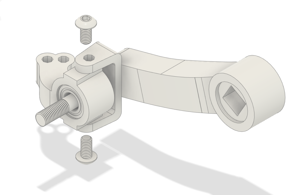
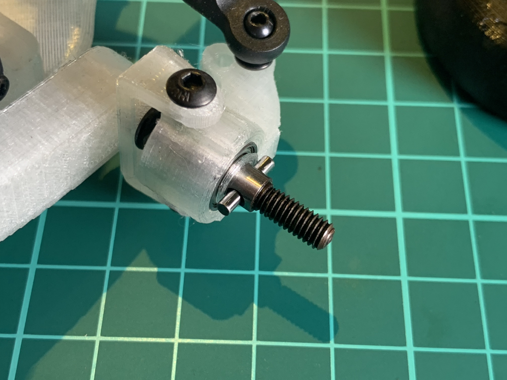
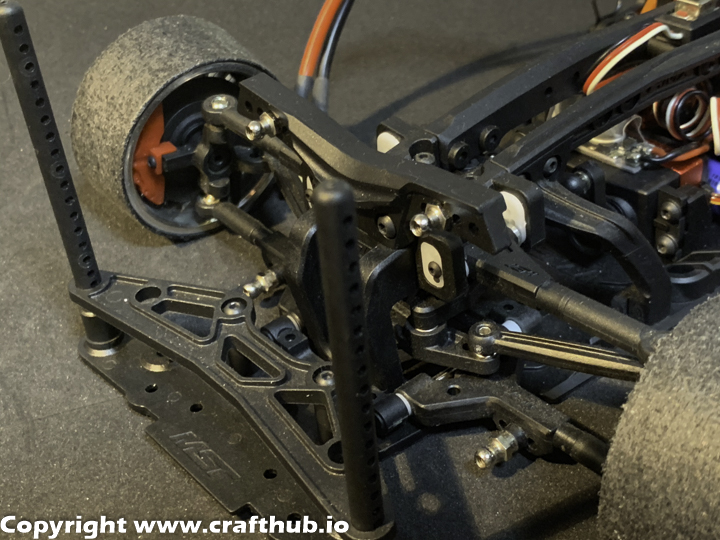
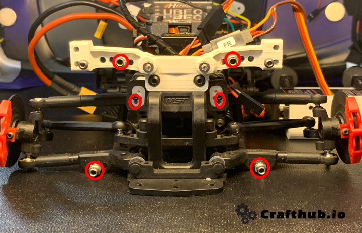
5, Front axle assembly
Fix the knuckle clamps to the suspension arms using Sakura D5 M3*12 flat screws.5*10*4Ballbearing. axle bolt.
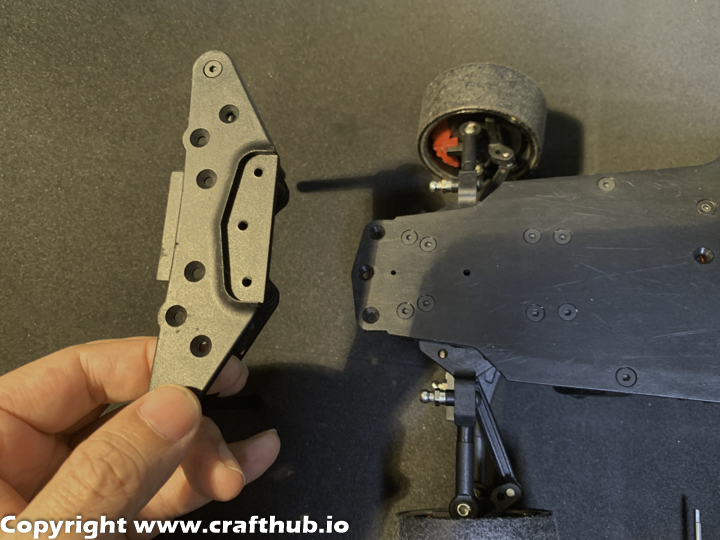
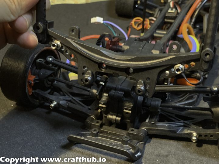
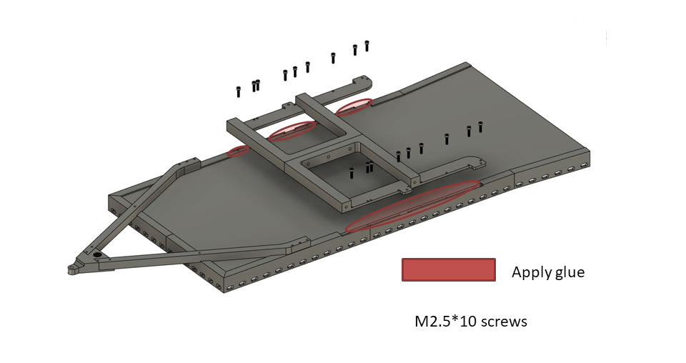
6, Brace installation
Install the battery holder.The front and rear braces are attached with double side tapes.
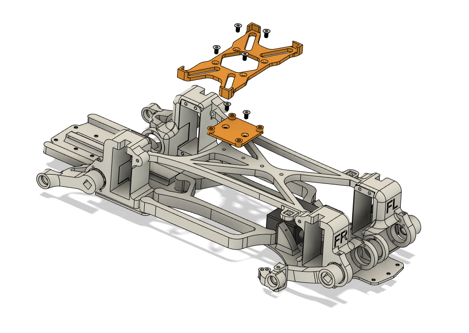
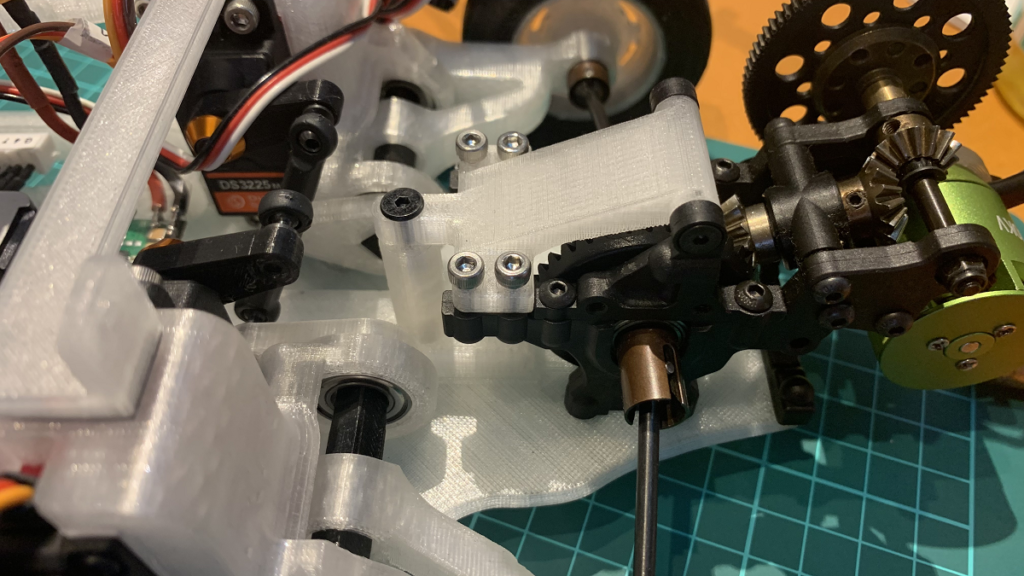
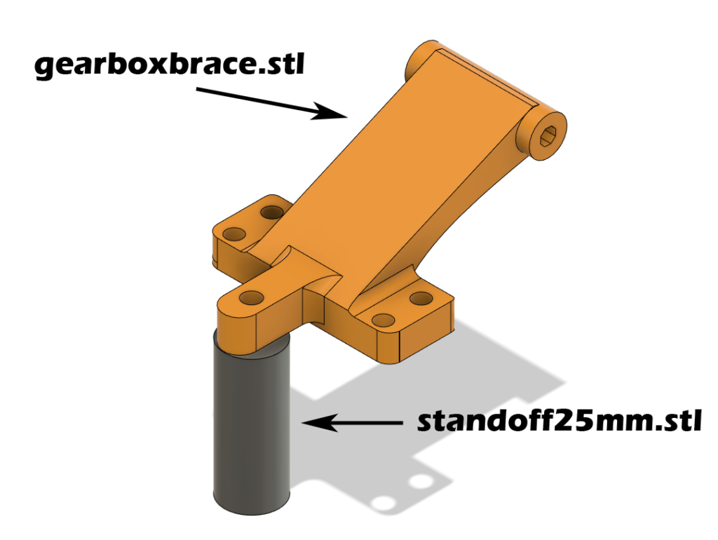
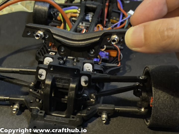
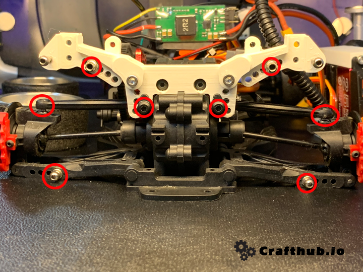
7, Drivetrain
Use standoffs and gearbox braces to ensure frame plate rigidity.
The gearbox brace is also used as an ESC mount.
Fix standoffs from the back of the rear frame as well.
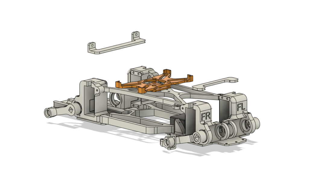
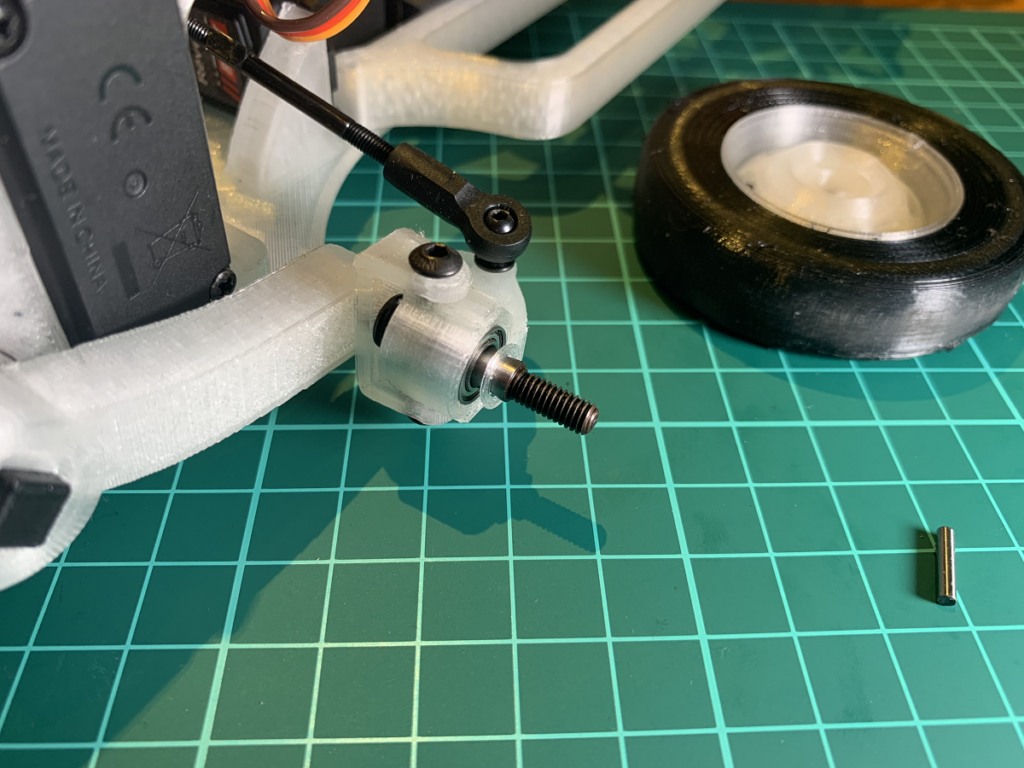
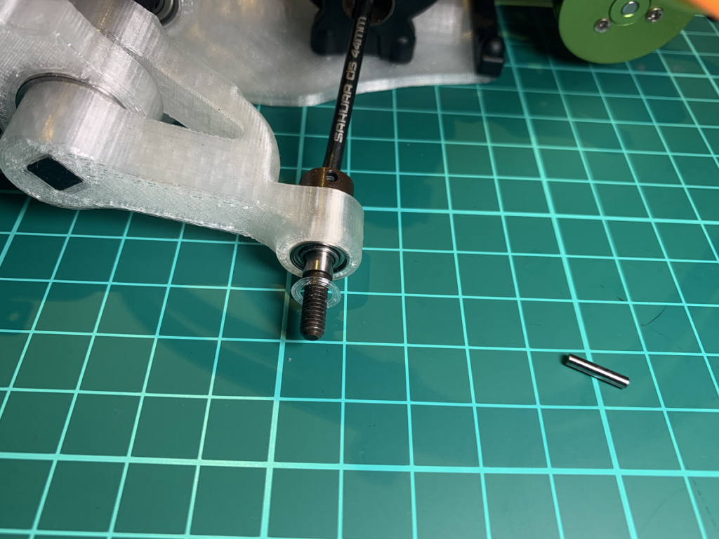
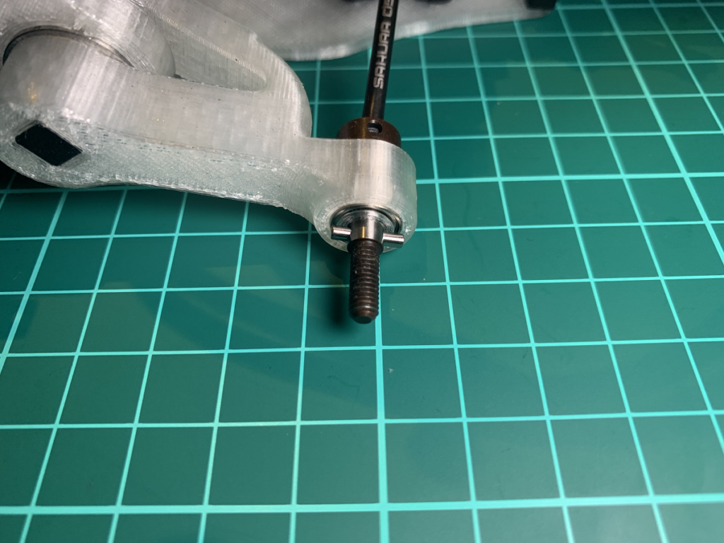
8, Axle with washer
Front axle with 0.5mm washerdone!Rear axle with 0.5mm washerdonewheel back side.
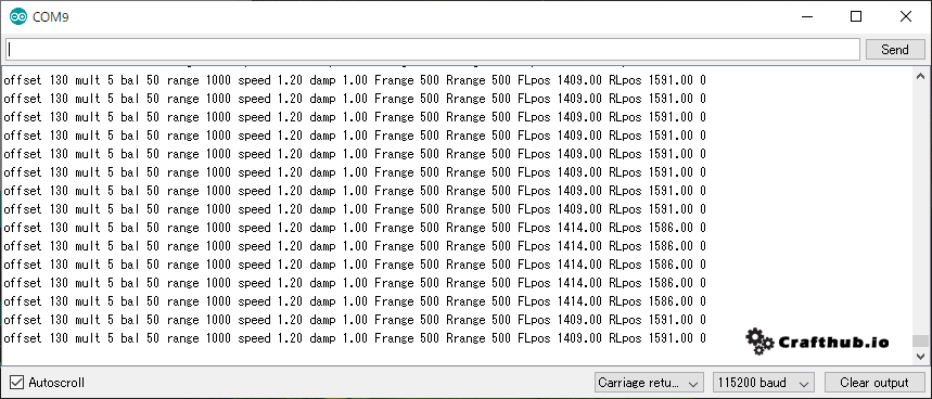
9, SSunit tuning
offset 0
multi 3
Bal 45
Range960
Speed 2.0
Damp1.0
Slice
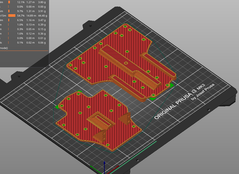
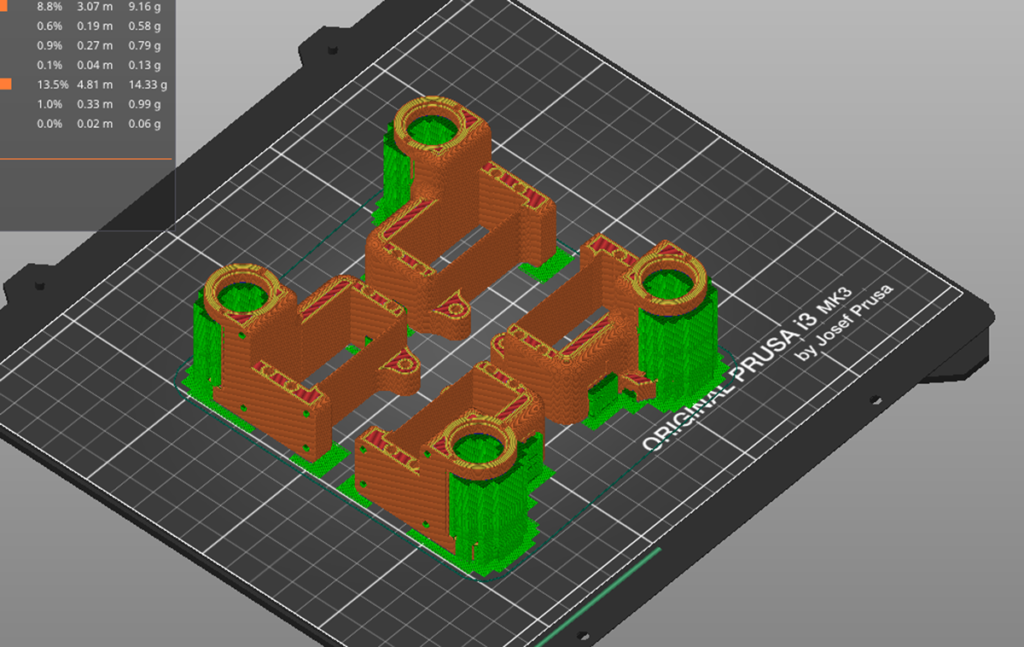
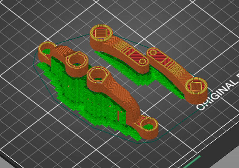
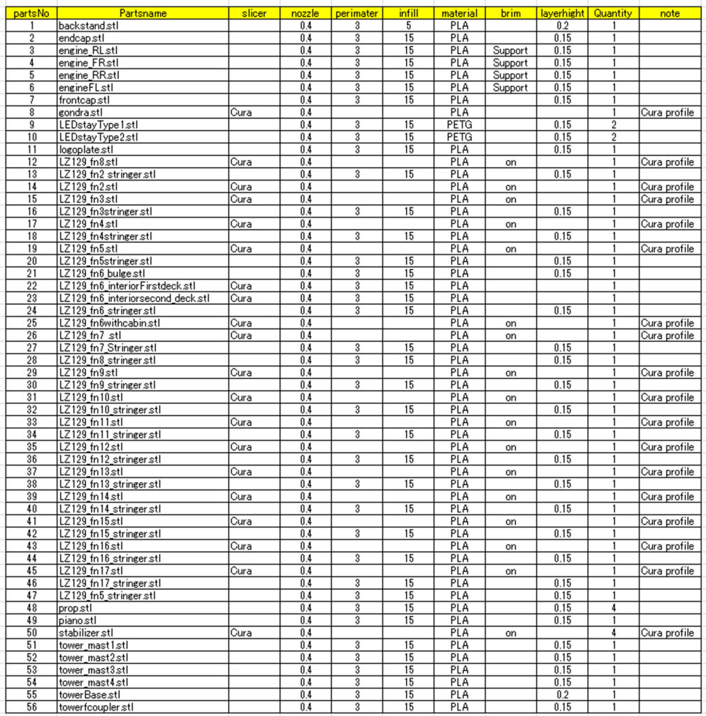
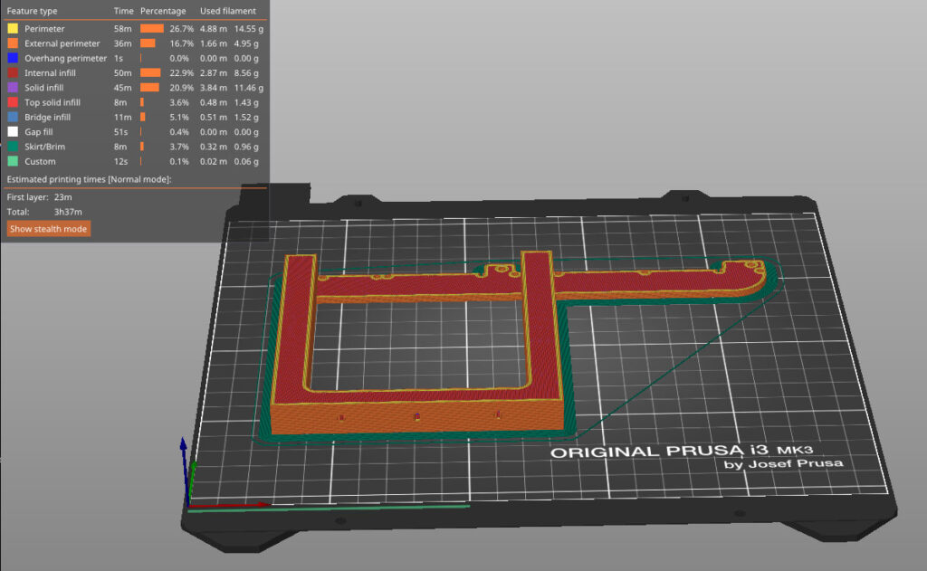
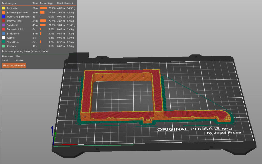
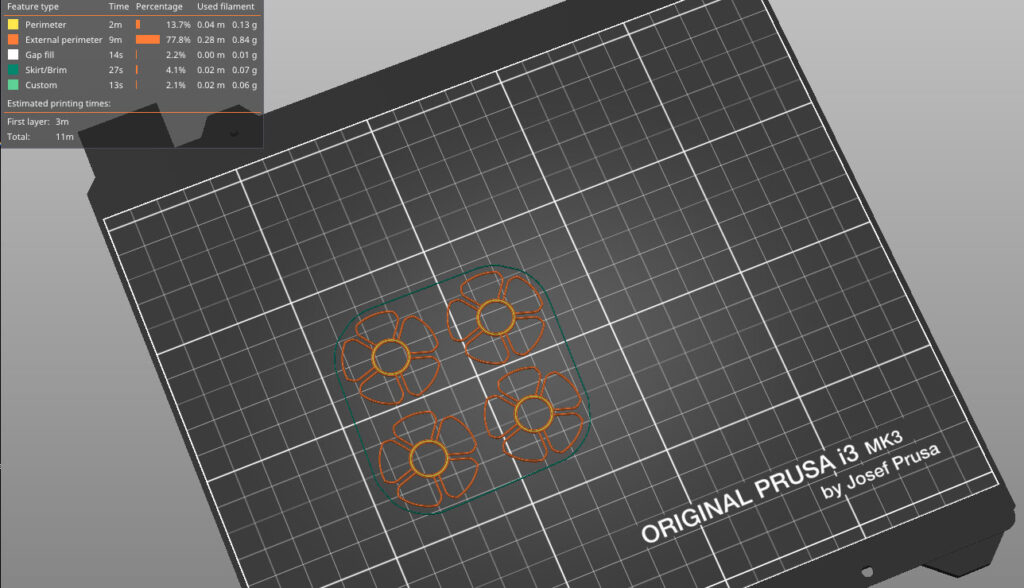
How to get the STL Data
You can Download this model`s Full STL data from crafthub.io
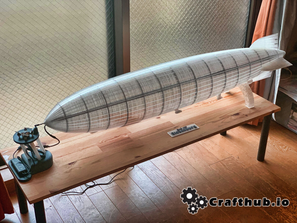
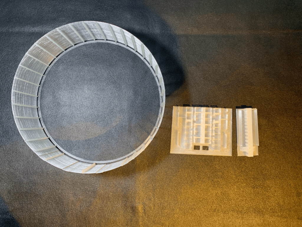
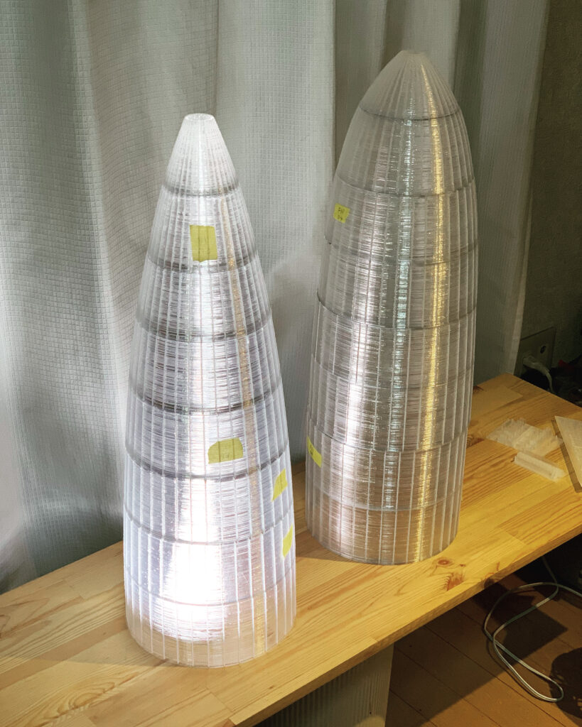
This is a scale model of 1/200 Hindenburg airship. The unique stringer rib construction reproduces the realistic skeleton of the Hindenburg, as well as the passenger cabin and gondola, and engine car are also incorporated.
It can also be used as a beautiful interior light by incorporating LED tape lights.
Note
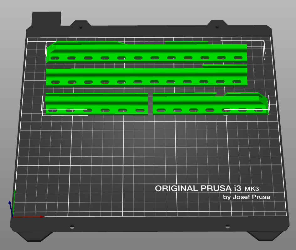
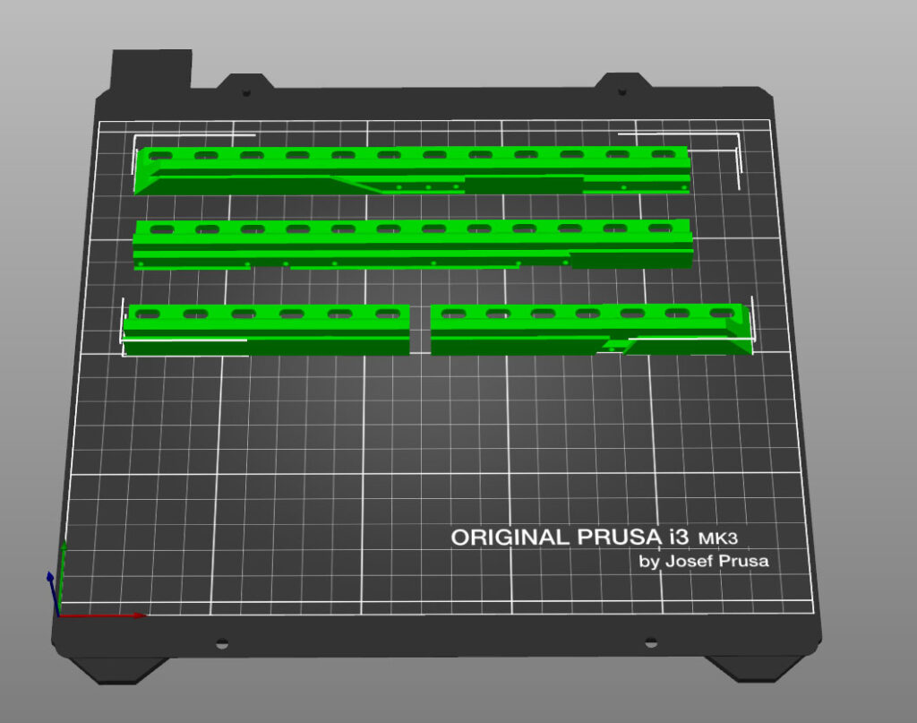
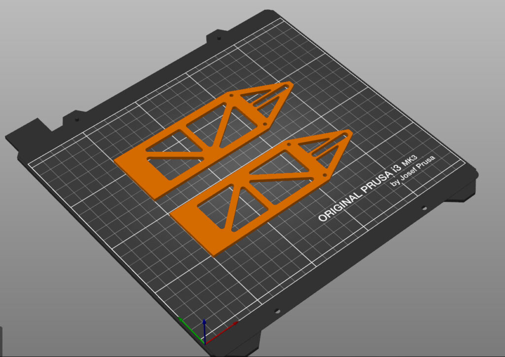
Please scale the data according to the size of the build plate of your 3D printer. Example prusaMk3s 98%. Length 1200 mm
The STL data in this kit must be uniquely sliced. For this reason, we have included data that has already been Gcode-ized.
To slice STL data properly, CURA is required, so please download CURA if necessary. Detailed configuration profiles for Cura’s PLA filaments are also included in this kit.
Slice1
When slicing with Cura, please use the profile data included in the kit.
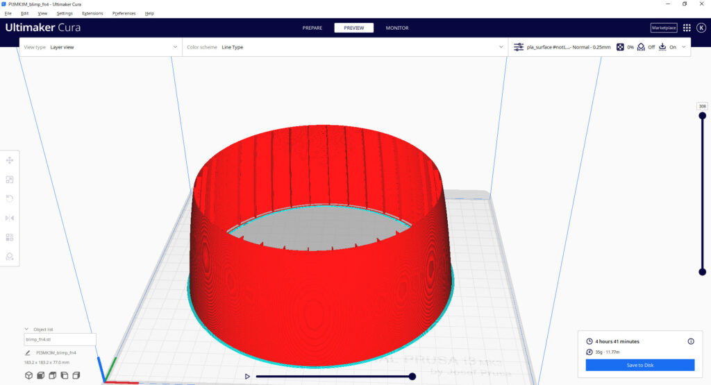
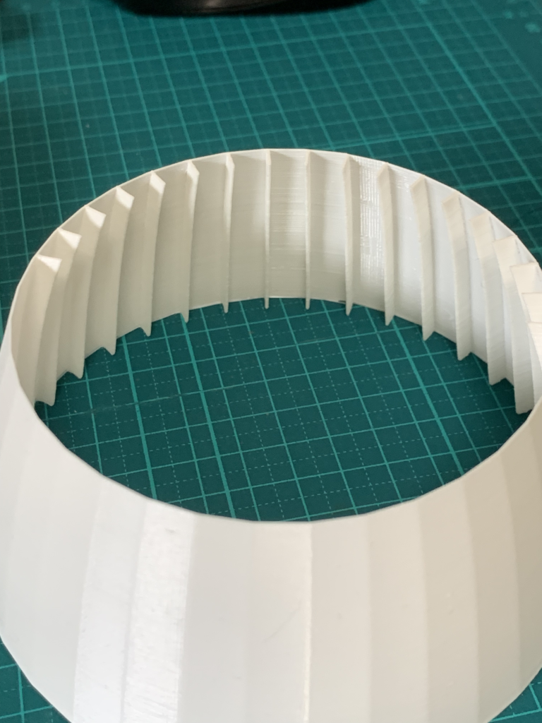
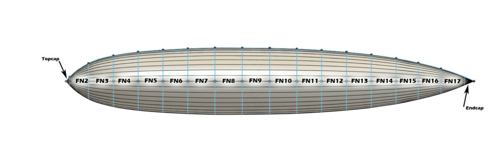
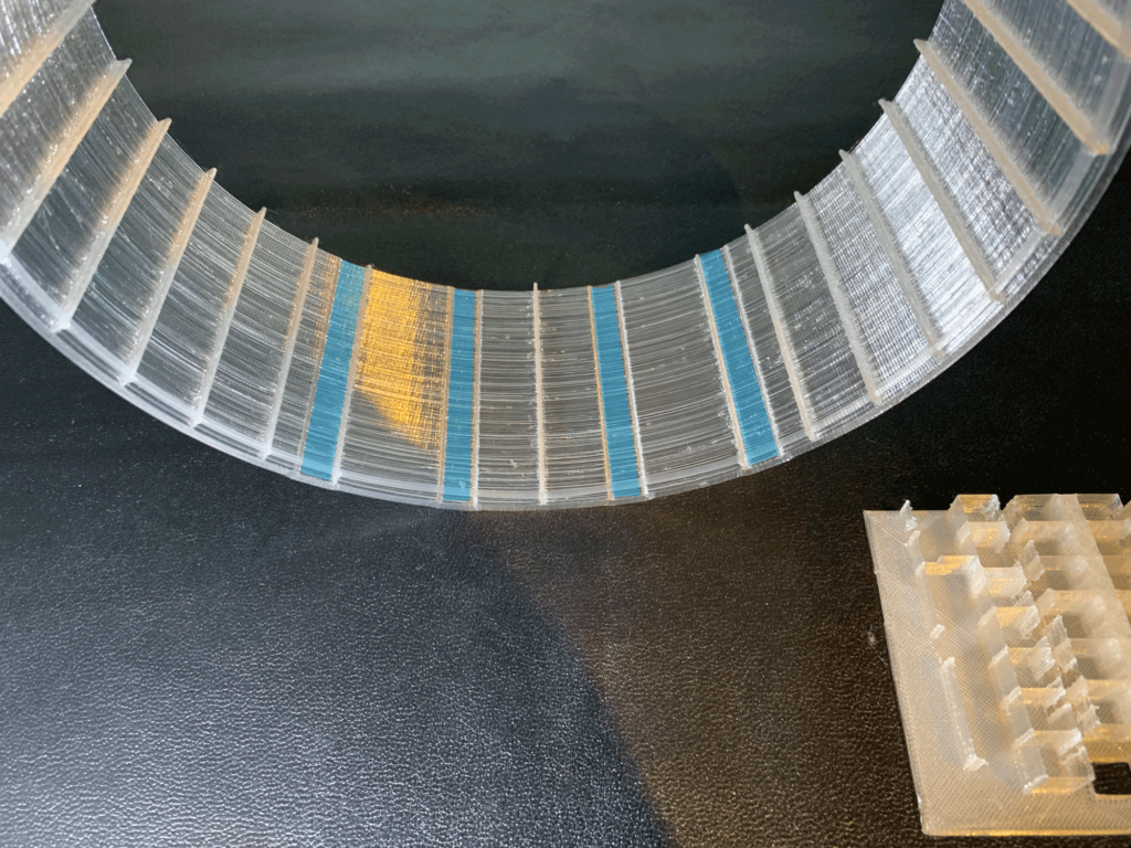
The airship is divided into 17 frames, each of which is pre-built with ribs every 10 degrees. By slicing this data in spiral vase mode, a stringer rib structure is formed.
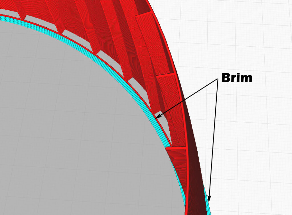
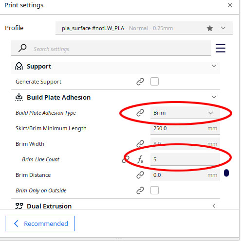
Brim
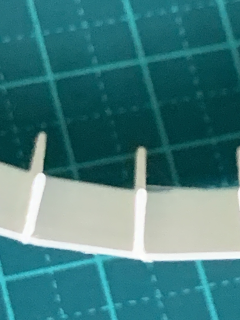
Because of the small footprint of the build plate, the adhesion of the first layer is very important. Both the inside and outside brim should be set.
After molding, the outer brim is removed cleanly with a design knife or similar tool. The inner brim is used to join the other frames, so it should be left in place.
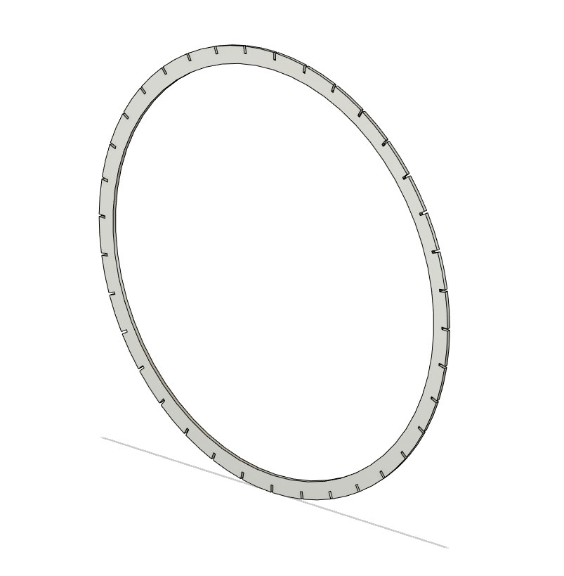
Frame and Stringer assembling
This section describes the process of attaching the Stringer to the FN4. Slide the Stringer from the bottom of the frame to the top, making sure it is flat at the very top, and secure the Stringer with CAglue. Use the minimum amount of CAglue necessary to avoid discoloration to white.
Tips
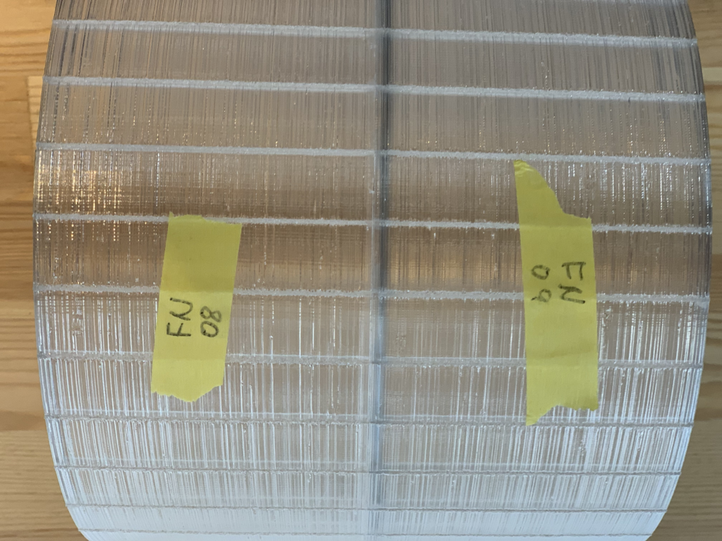
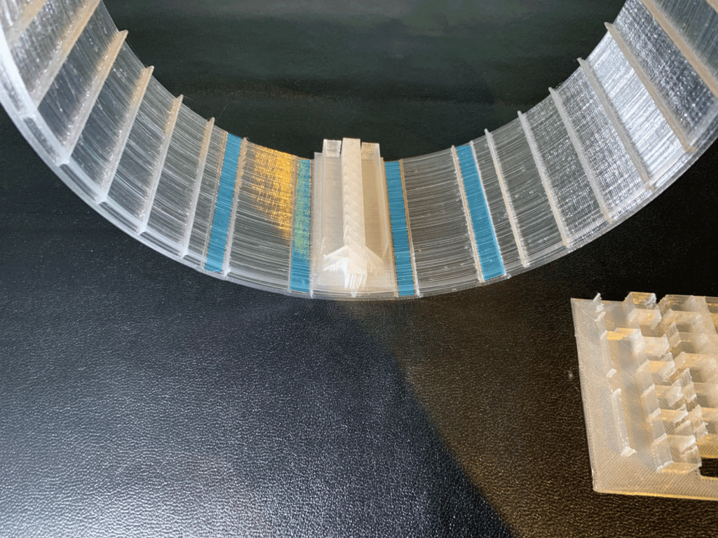
Install the STRINGER on all 17 frames in the same manner. The correspondence between frames and stringers is as follows.
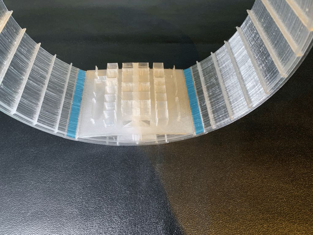
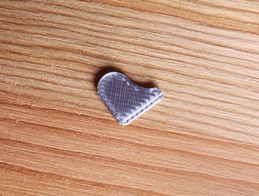
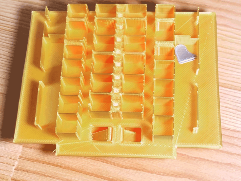
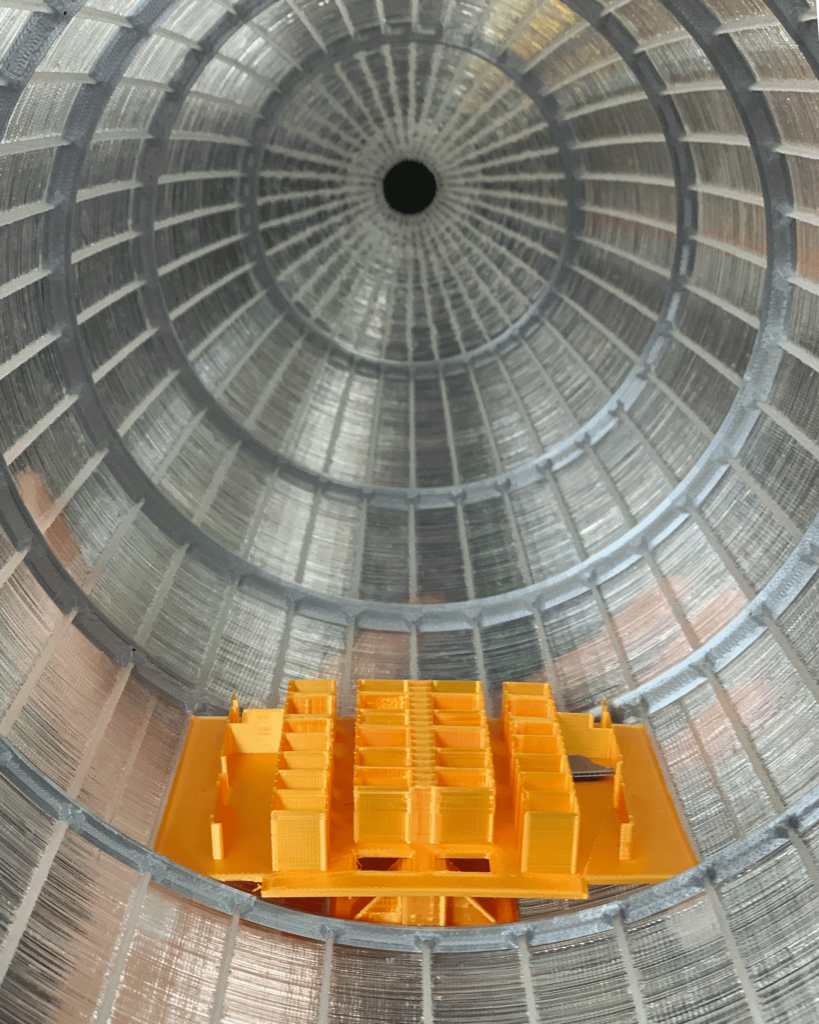
The structure of FN6 is slightly different from other frames. Windows that allow you to see the ground from the lounge and the two-story guest room, and an aluminized grand piano placed in the lounge.
Blue represents windows
First passenger Floor
Second passenger floor and lounge.
legendary aluminum grand piano
put the piano onto the floor.
Build up the frame
The front side is assembled from FN2 to FN9, and the rear side from FN10 to FN17. The assembly of the frame will be stopped here in order to install the LED lights in the airship.
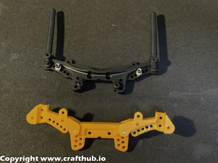
This kit is an STL Data kit for conversion of MSTRMX2.0 chassis with an active suspension system ”SuperScale2k20 SS Unit”.
Future
• Come with All of the printable parts, without SS unit. • Design for MST RMX2.0 • Active suspension and conventional suspension hybrid. • Simple and reliable, easy to swap design • Fully compatible original suspension geometry
What is contained in this kit?
What you need (items not included in kit)
Superscale2K20 SS unit kit
BEC unit
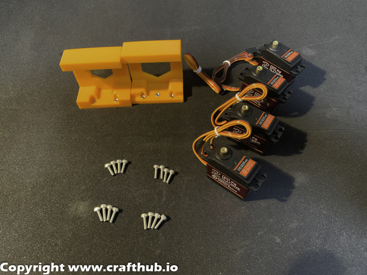
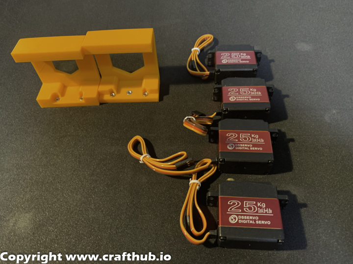
High torque Servo *4
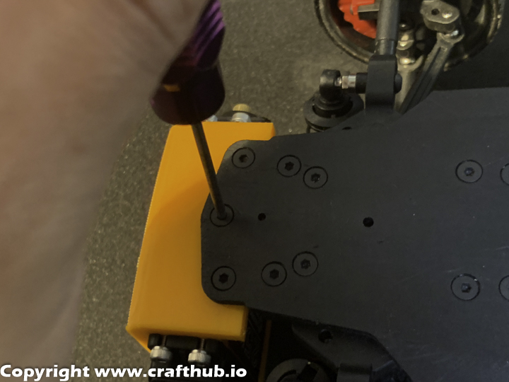
1, Installation
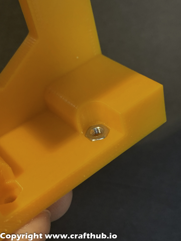
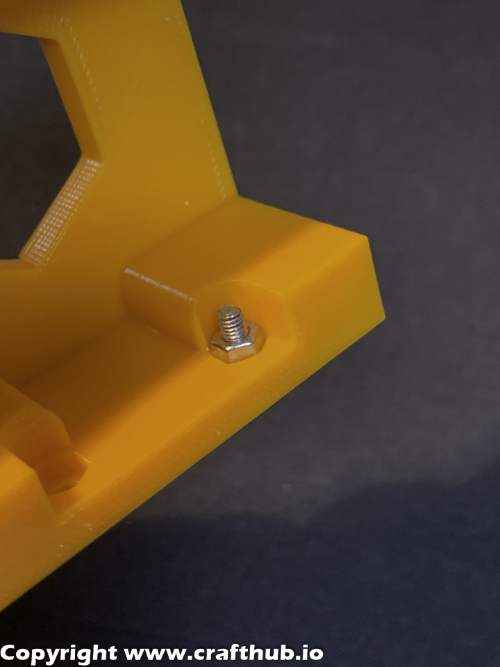
The M3 nut will be flush when it is installed correctly
Use the M3 screw, M3 Nut, and gently insert to the M3 Nut position.
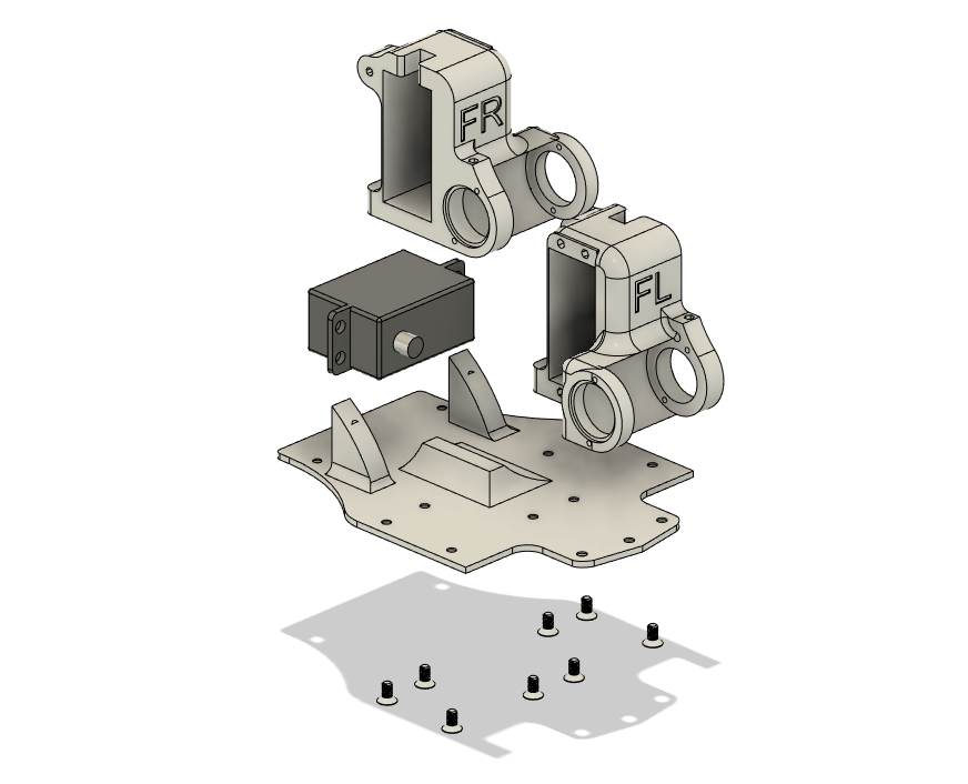
2, High Torque Servo installs
Use M3*10 CapScrew to screw servos to chassis mount brackets.
The mount screw hole size is 2.8mm and optimizes the tolerance for M3 screws. The Servo’s output shaft should be on the side closest to chassis mount holes.
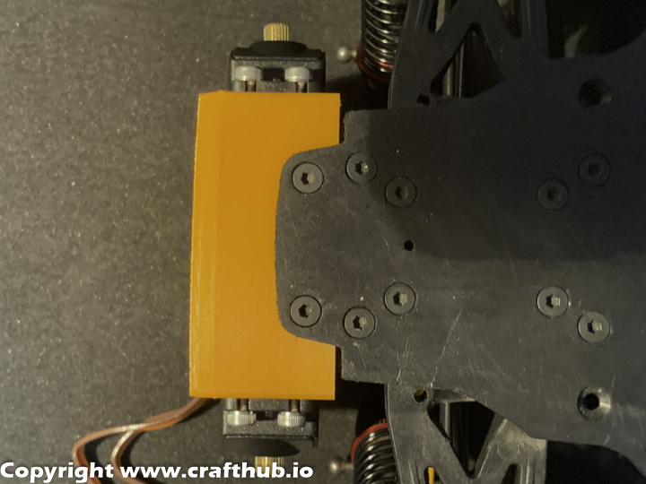
3, Remove the bumper
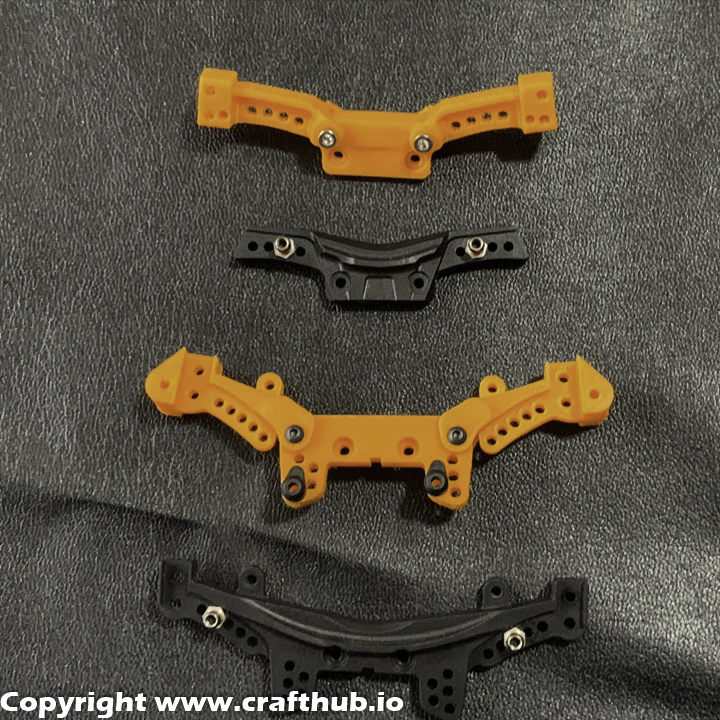
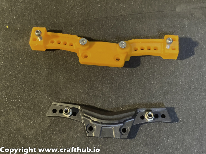
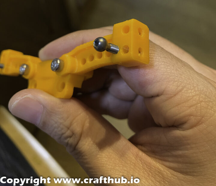
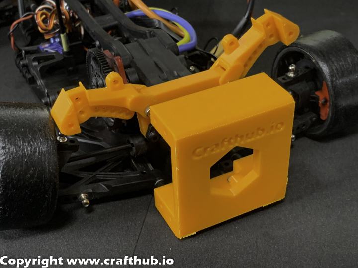
4, Swap the Strut tower bar(Front)
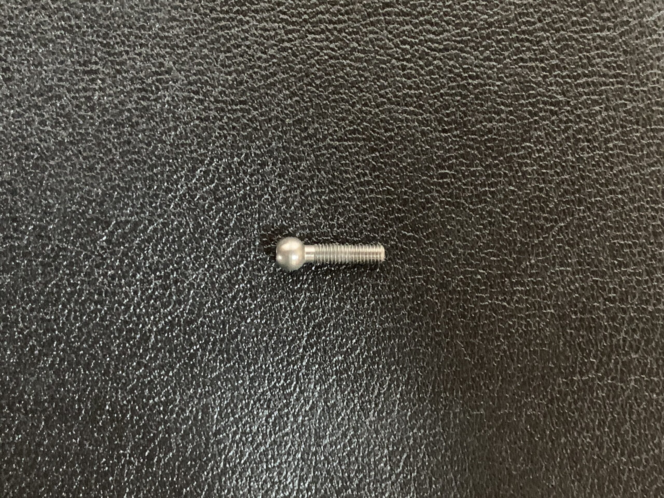
Remove the original Strut Tower. Remove the ball end and fix it in the same position
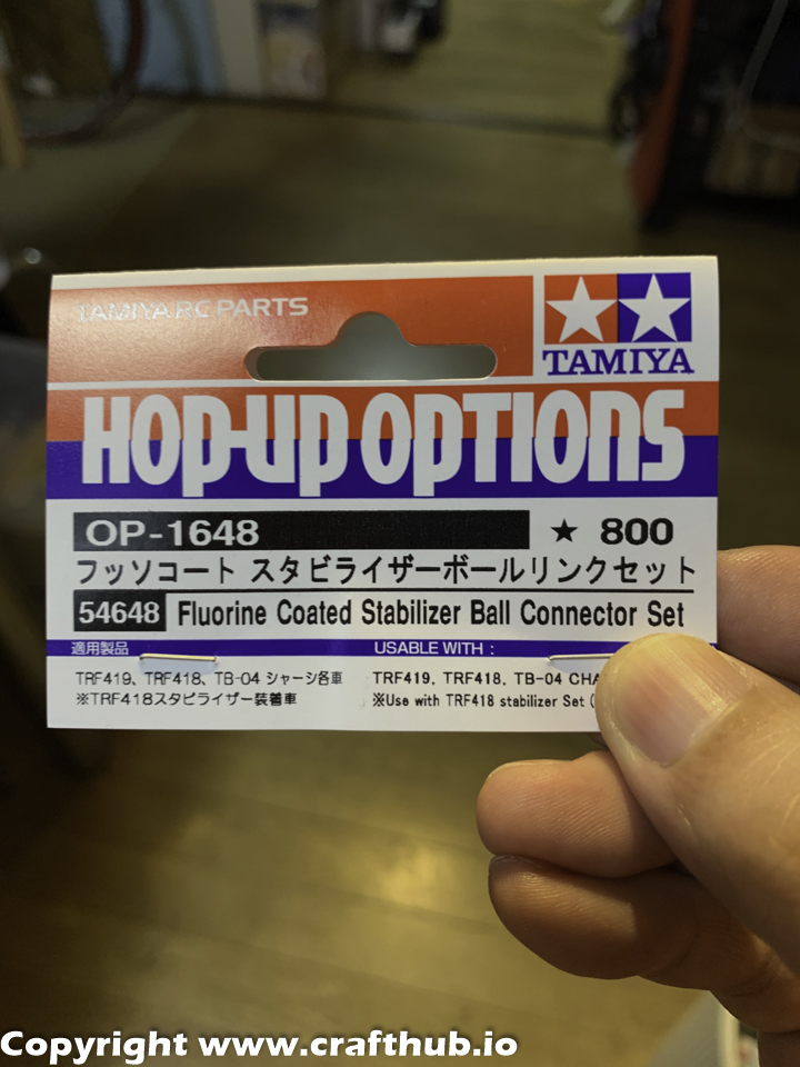
Use a Tamiya Fluorine coated Stabilizer Ball connector set For the front, use this one. (partsNo17)
Assemble the front Strut tower by adding M3*15 screws for the front. Do not over-tighten. Check for minimum play and movement.
The assembled strut tower needs a little bit of friction. If this part is too loose, the SS’s multiplier value can’t increase, and serious oscillation will occur and won’t stop. However, regular suspension linkage parts have to always be very smooth.
5, Swap the Strut tower bar (Rear)
Assembling the Rear Strut tower: (Assembled)
Using M3*12 screw for the Rear. (Do not over-tighten) Check minimum play (The arms should move easily.)
The assembled strut tower needs a little bit of friction. If this part is too loose, the SS’s multiplier value can’t increase, and serious oscillation will occur and won’t stop. However, regular suspension linkage parts have to always be very smooth. Use a Tamiya Fluorine coated Stabilizer Ball connector set For the Rear, use this one. (partsNo17)
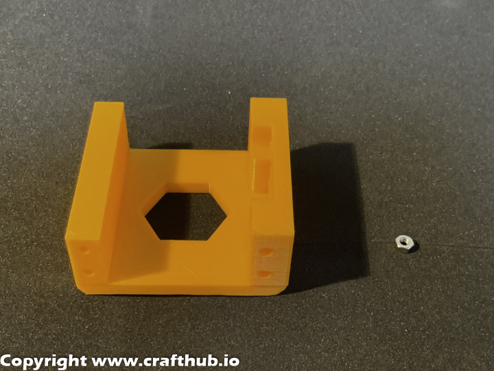
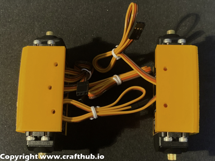
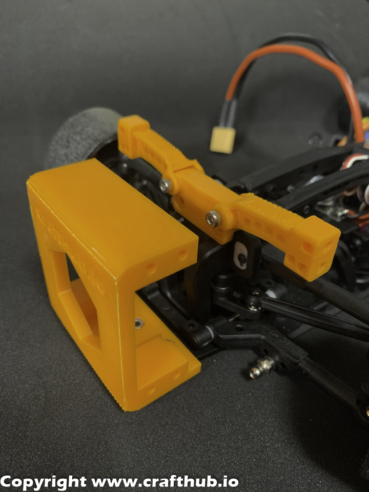
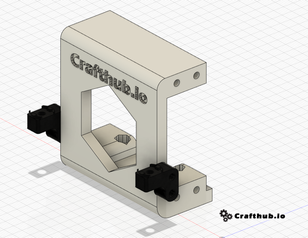
6, Mounting the servo holder
Front
Side screw use 3*15 Countersunk screw. For the center screw. Use the screw that MST originally used.
The *Front servo holder has 3 screws. The rear servo holder has 2 screws.
Rear
Remove the original bumper and replace it with the Servo holder. About the Rear screw. Use the screw that MST originally used.
7, Initial setup of SS unit.
Firmware needed from SuperScale2k20
SUPERSCALE_V1.2.ino.hex
*This firmware is pre-installed
8, How to setup SS unit
You need to install Arduino configuration software. Please download it from the link below.
You may download Arduino IDE software for your suitable platform. macOS or Win
SSunit setup Step1
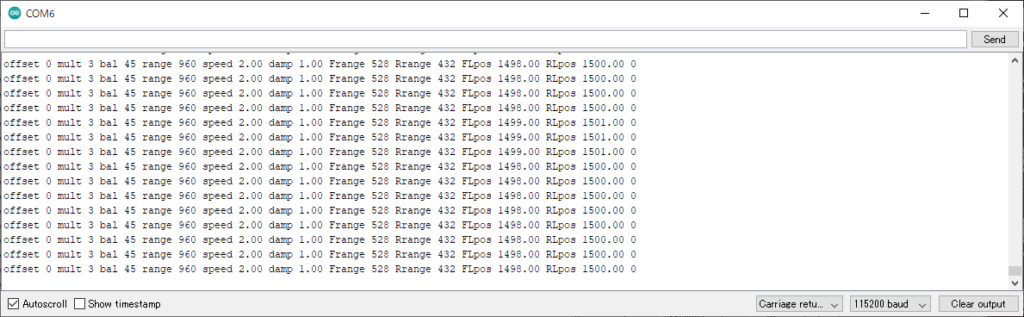
First, connect the SS unit to the PC and set the offset to 0.
Next set BALANCE to 50.
The servo‘s neutral PWM value is almost 1500
FLpos 1500
RLpos 1500
*you should provide the power for SS Unit cause USB doesn’t provide enough power to move the servo neutral position.
Step2
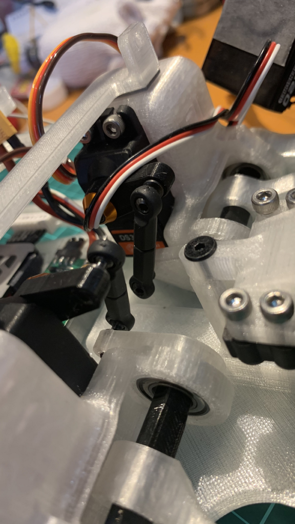
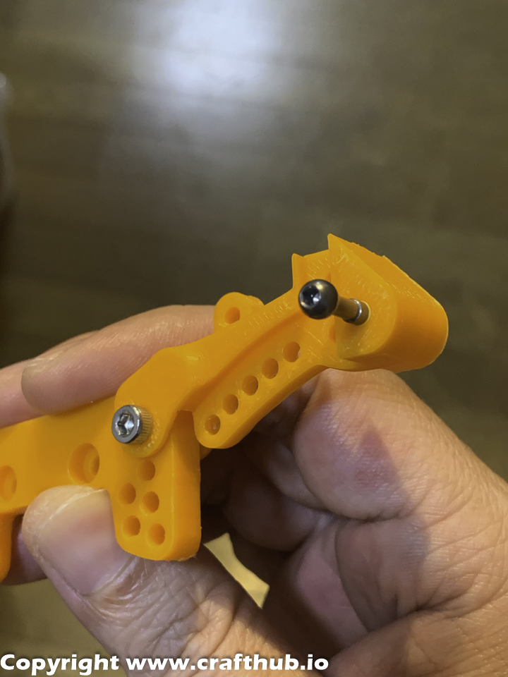
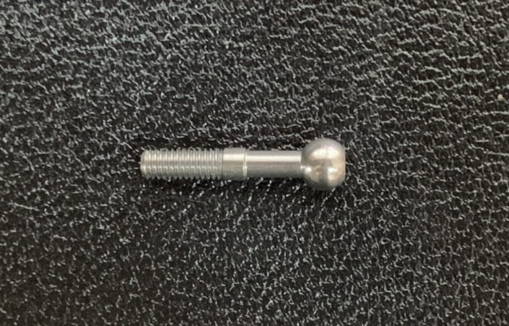
Check all of the 4 servos in the neutral position, and then Set the servo horn like this.
Servohorn and endball fix with M3x8 cap screw.
This hone has a tapered servo shaft connection, so any spline servo can perfectly fit this servo horn. so this servo horn material is PETG. Use with Tapered washer like in the photo.
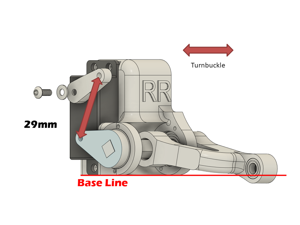
Step3
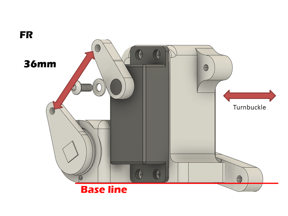
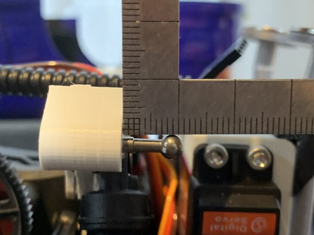
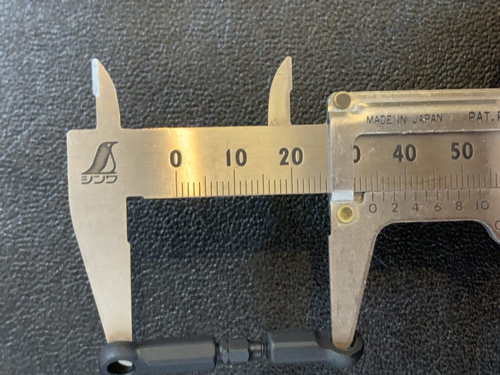
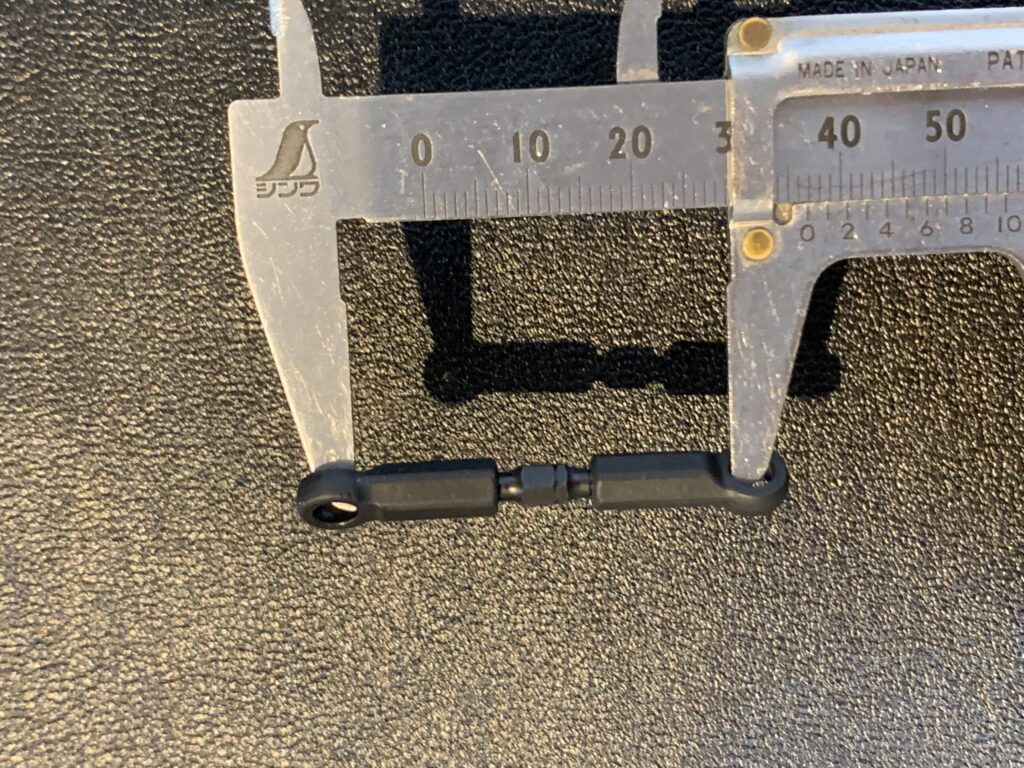
Adjust The turnbuckle length, and then connect the servo and Strut arm.
front=34mm
Rear=37mm
All about the physical setup is done, please test the sample setting value.
MST sample setup value
This is the start value to set up the active suspension
For more detail, please refer to SS unit manual.
Front side ball end position
Rear side Ball end position
It will be better to change more high viscosity dumper oil.
Ver2
Ver 2 servo holder is an integrated body holder
Disclaimer
Do not use this file for commercial purpose without any permission.
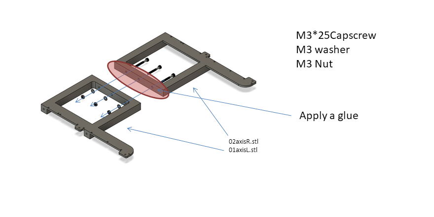
Yokomo 4.8mmφ Ballend can use a tow vehicle coupler.
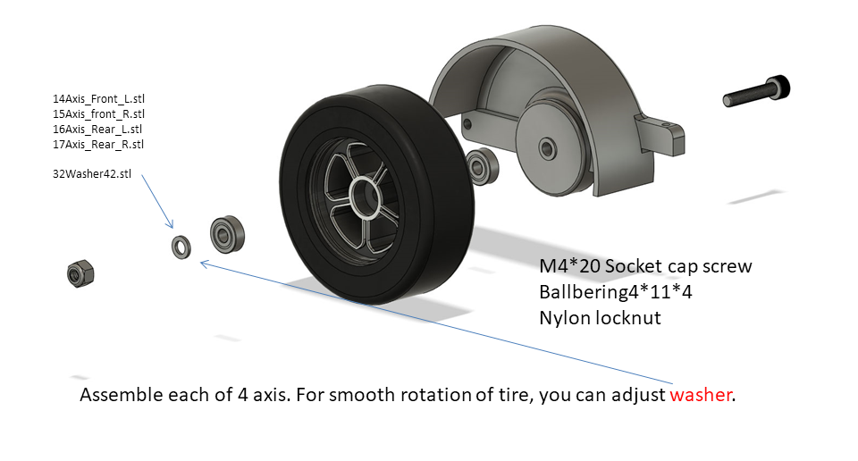
Assemble9
Assemble10
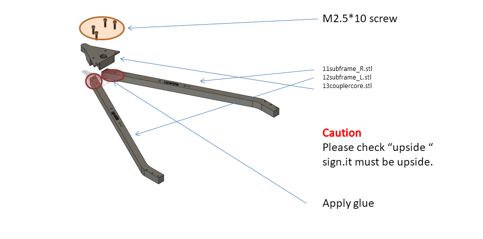
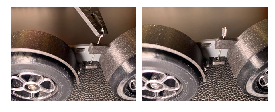
Assemble each of 4 axes. For smooth rotation of the tire, you can adjust it with a washer.
Assemble11
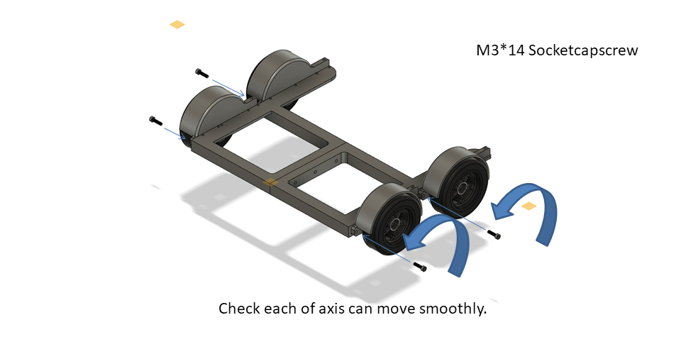
Assemble12
Assemble13
Assemble14
Assemble15
Assemble16
Assemble17
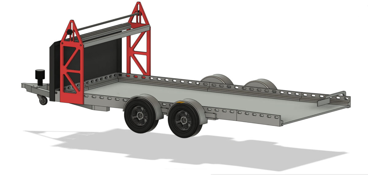
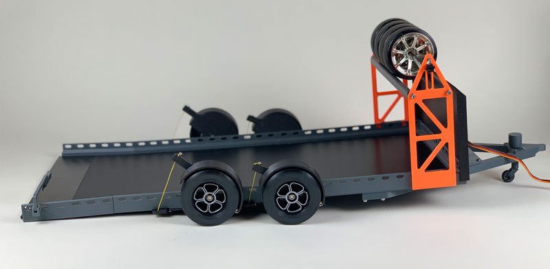
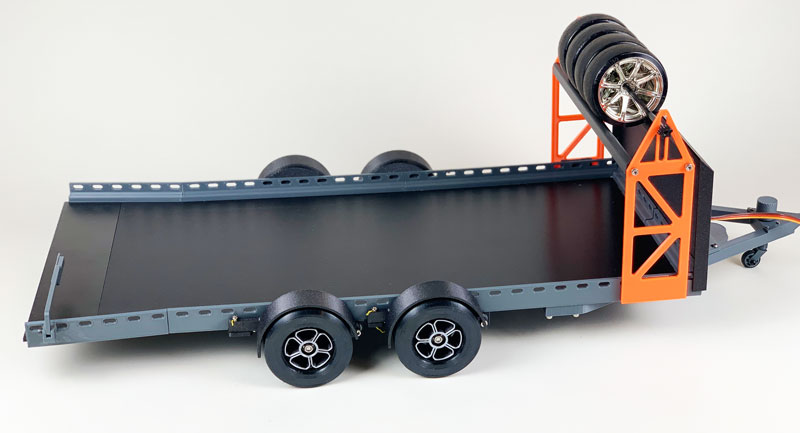
Assemble18
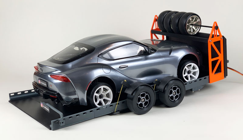
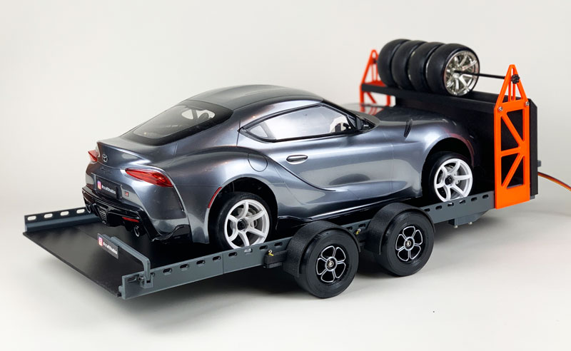
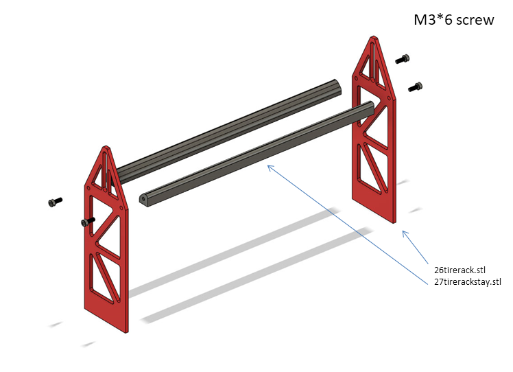
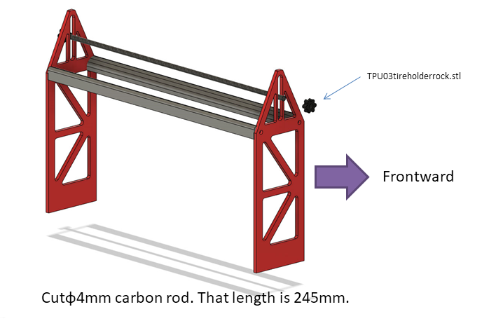
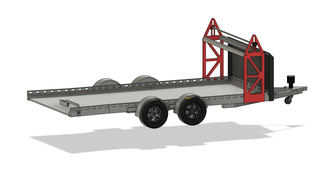
Mount the Tire rack use with double side tape. Take attention to the Tire rack direction.
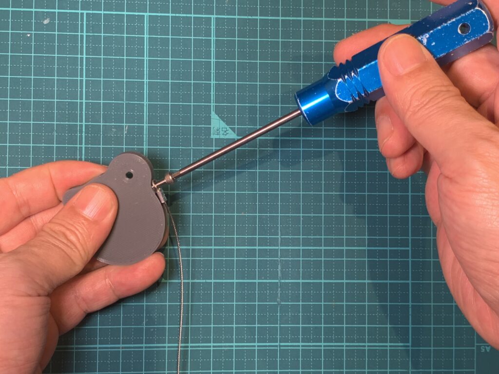
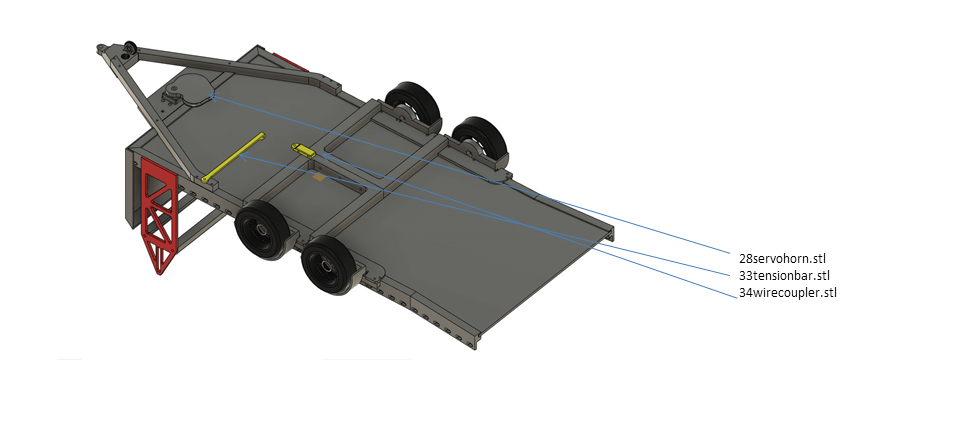
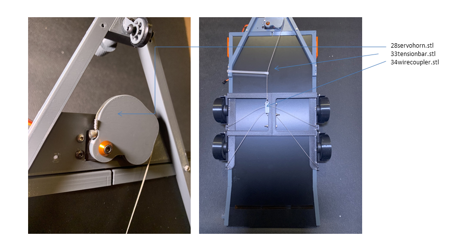
Retract mechanism
M3*8 screw Hangingwire0.8mm 28servohorn.stl
Running the wire like that and adjusting the tension.
Adjust the wire length and fix it.
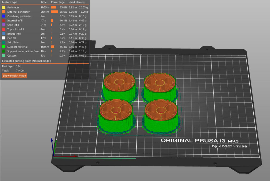
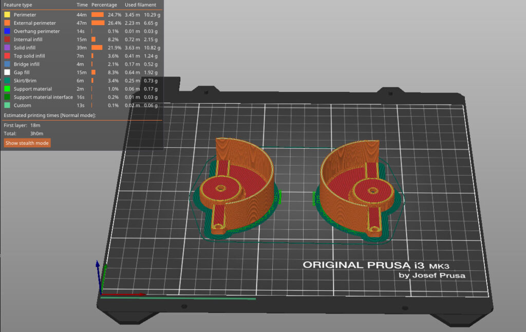
Slice Sample
Disclaimer
Do not use this file for commercial purposes without any permission. This model is designed to make FDM 3Dprinter, the parts have some additive markings, however, is no problem with those parts’ functions.