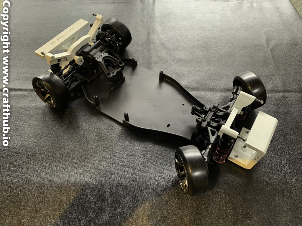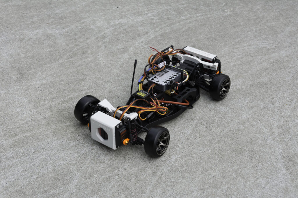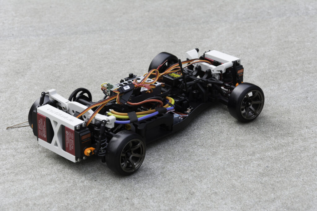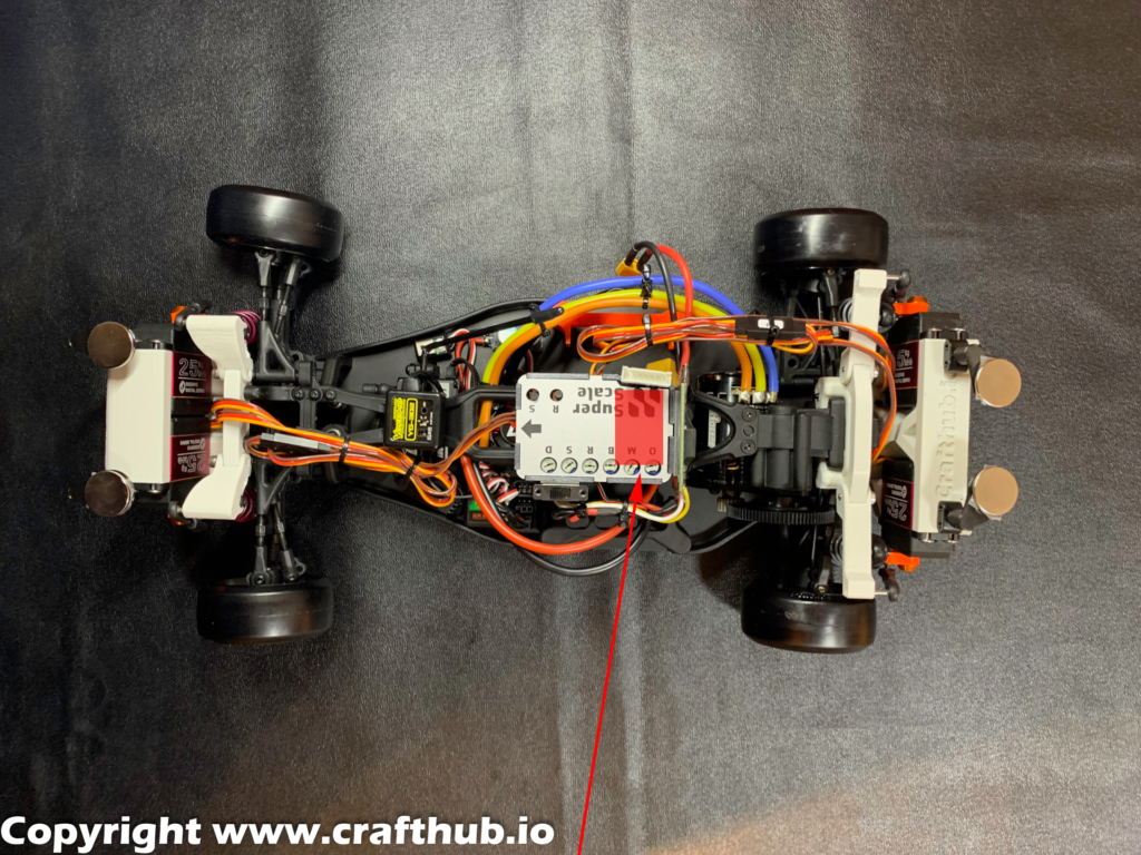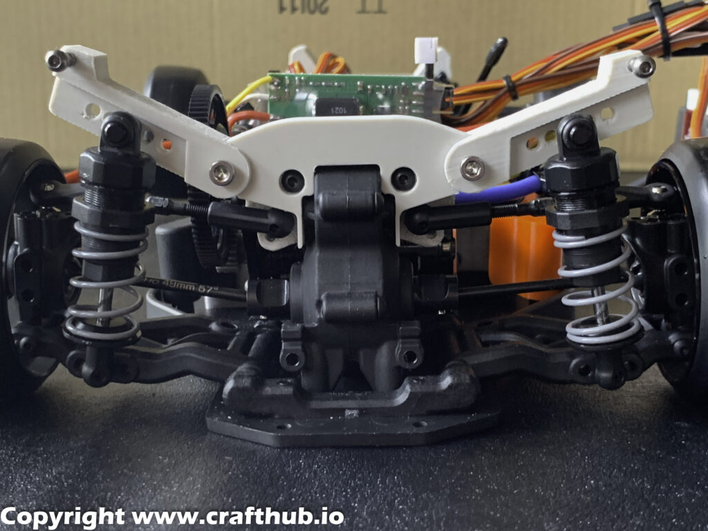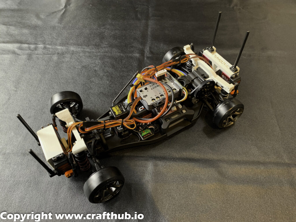
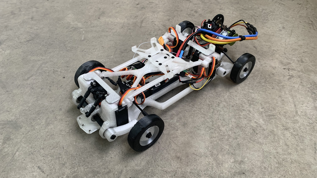
This kit is a chassis to use the Superscale2020 active suspension unit effectively. It features a compact package that combines torsion bars and active suspension in the size of the Tamiya M chassis (wheelbase 239mm).
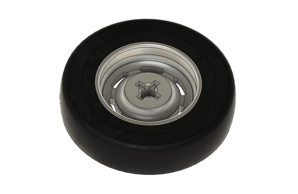
This model also uses gripped tires for a more realistic scale appearance. We recommend using a DC motor for the crawler or a multi-pole brushless DC motor to enjoy realistic behavior at very low speeds.
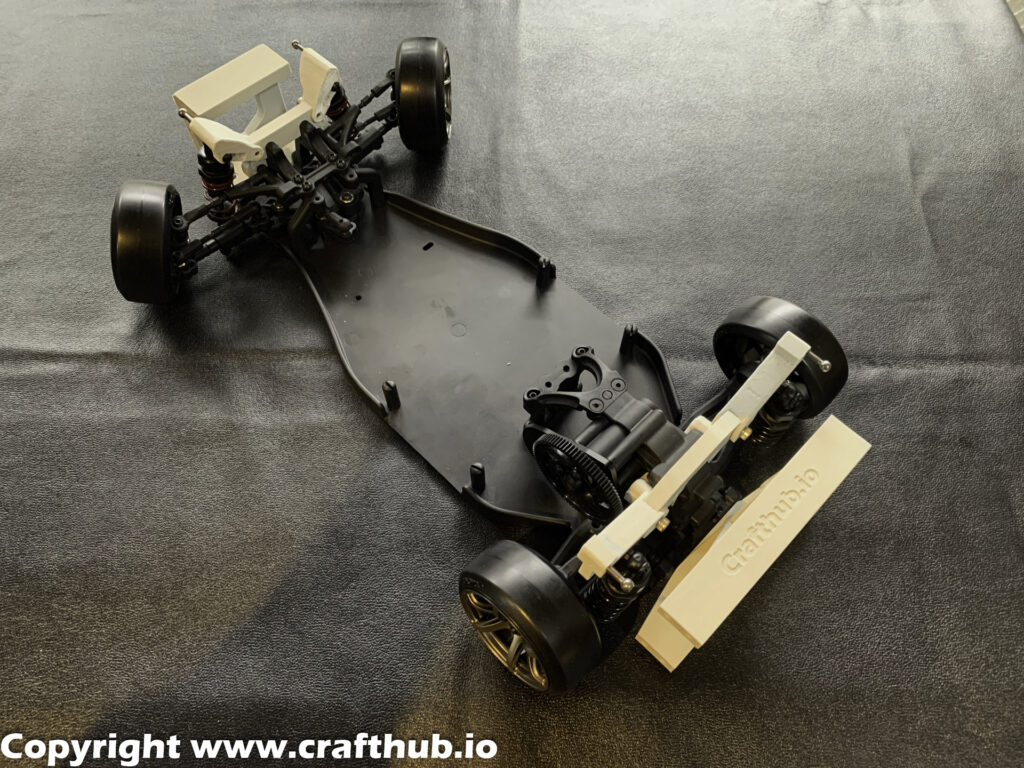
Drivetrain
The drivetrain of this kit is designed to maximize the use of Sakura D5 parts available to everyone. As a result, it is possible to use active suspension at a lower cost than collecting the necessary parts individually.
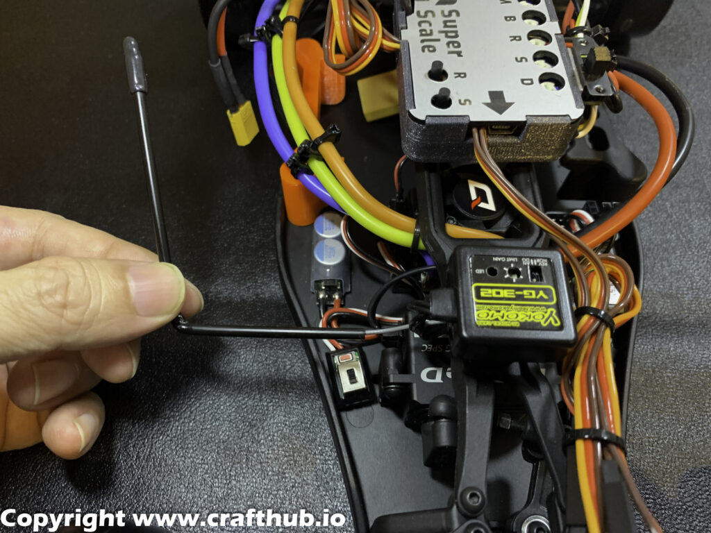
A steering gyro is not necessarily required, as the tires provide some grip.
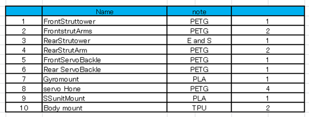
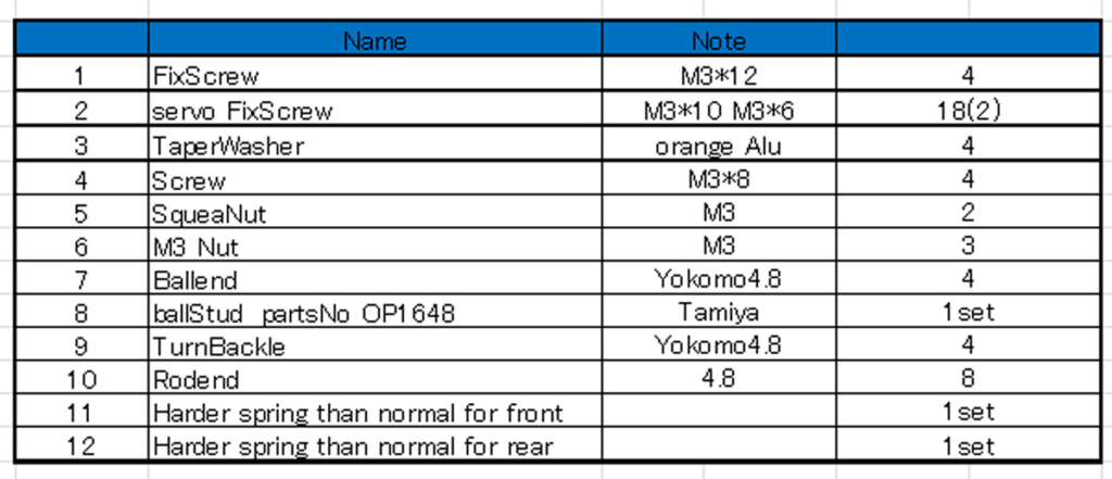
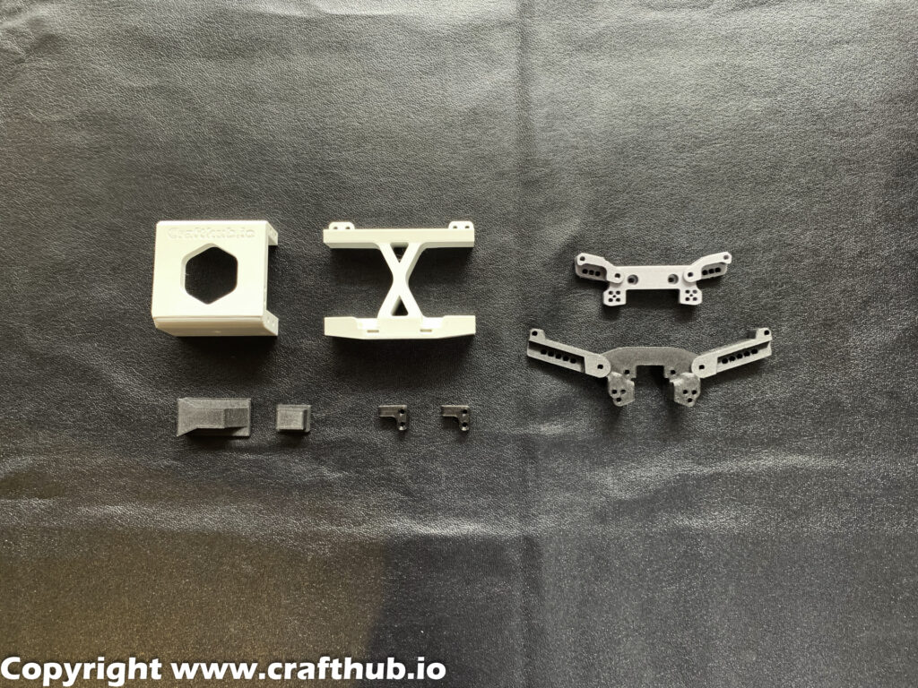
What’s included in the kit
What you need besides the kit
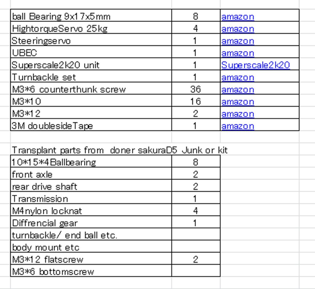
The list with active links can be downloaded from Google drive.
Superscale2020

The Superscale2020 “SS” unit is a key component of this chassis and should be purchased here.
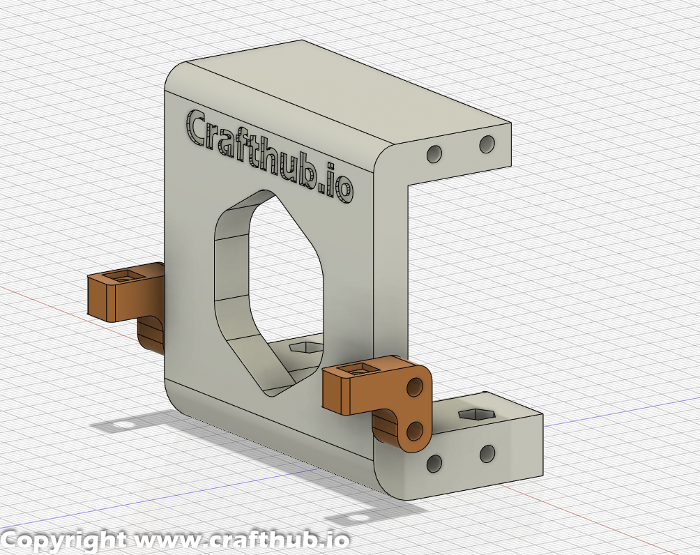
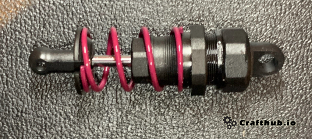
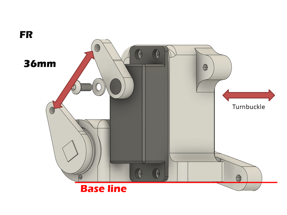
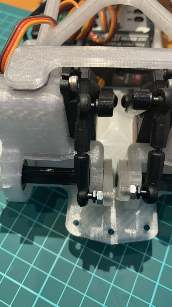
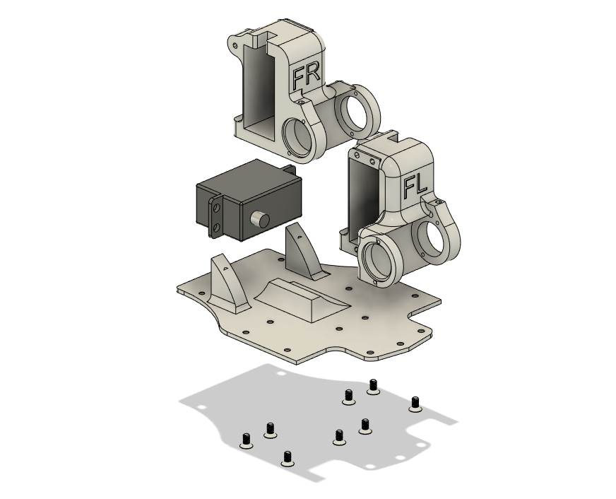
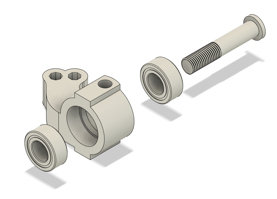
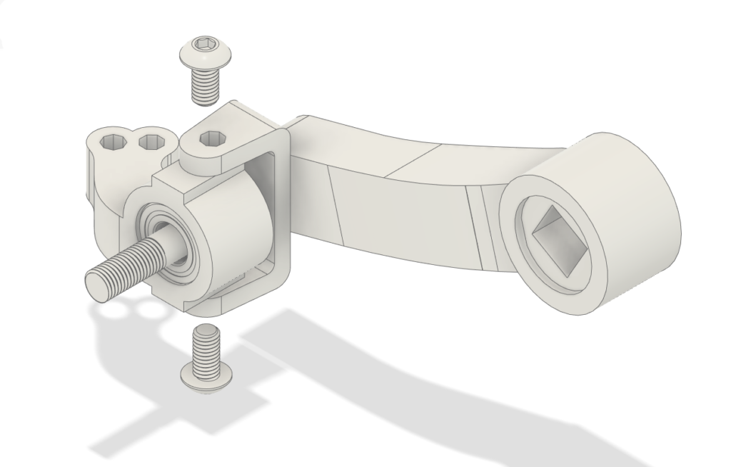
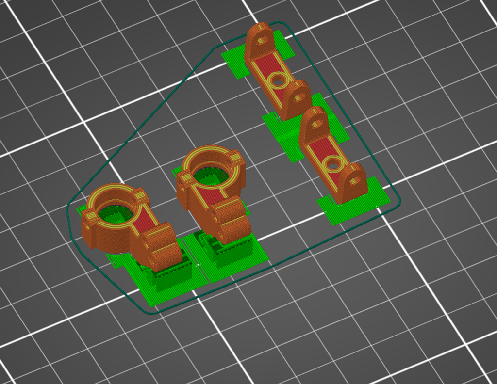
1, Servo and torsion bar box assembly
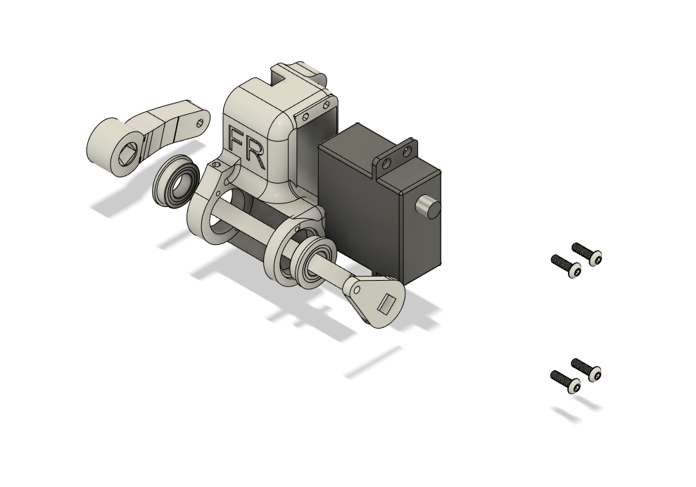
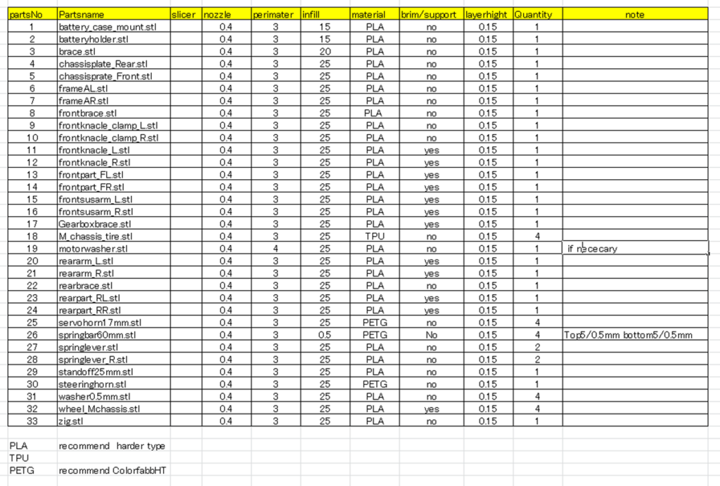
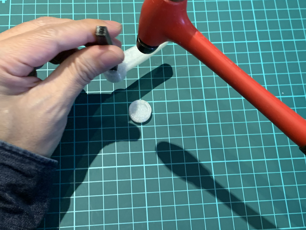
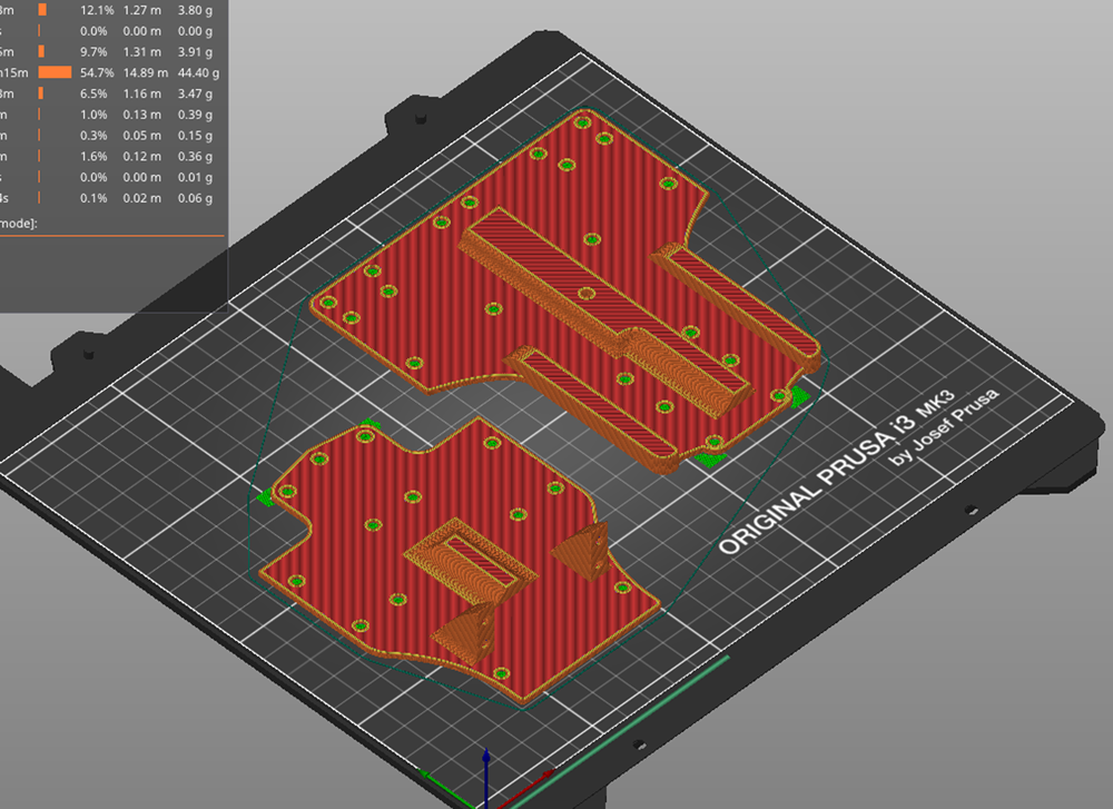
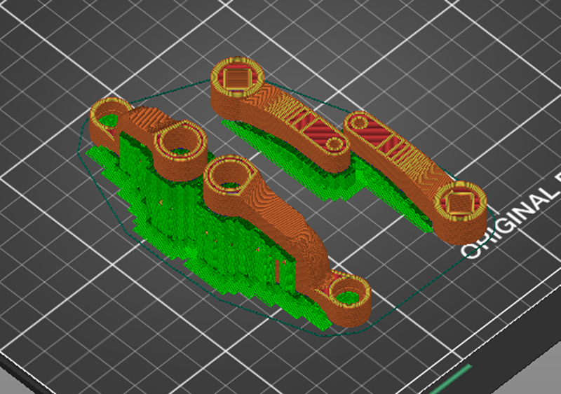
Torsion bars are printed with PETG. Please check the print settings.
Insert the torsion bar into the suspension arm. Use a rubber hammer or similar tool to gently drive it in; use a Zig to drive in the appropriate amount. Do not install the servo horn at this point.
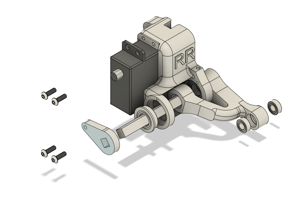
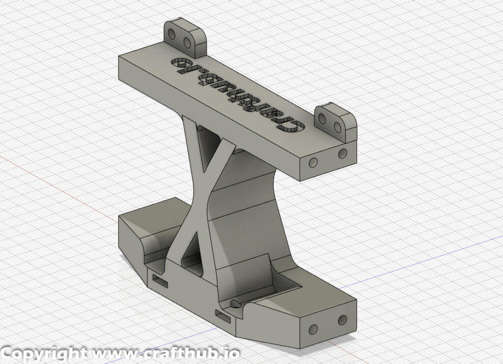
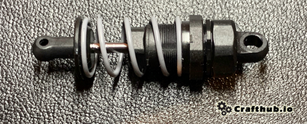
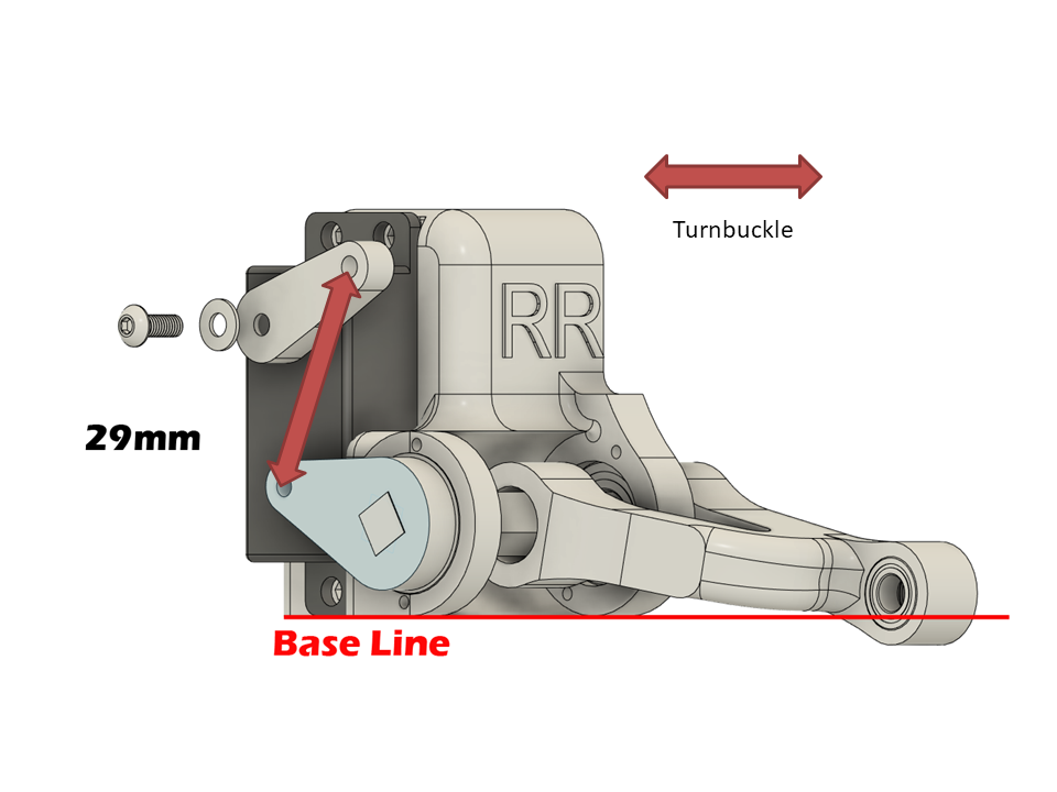
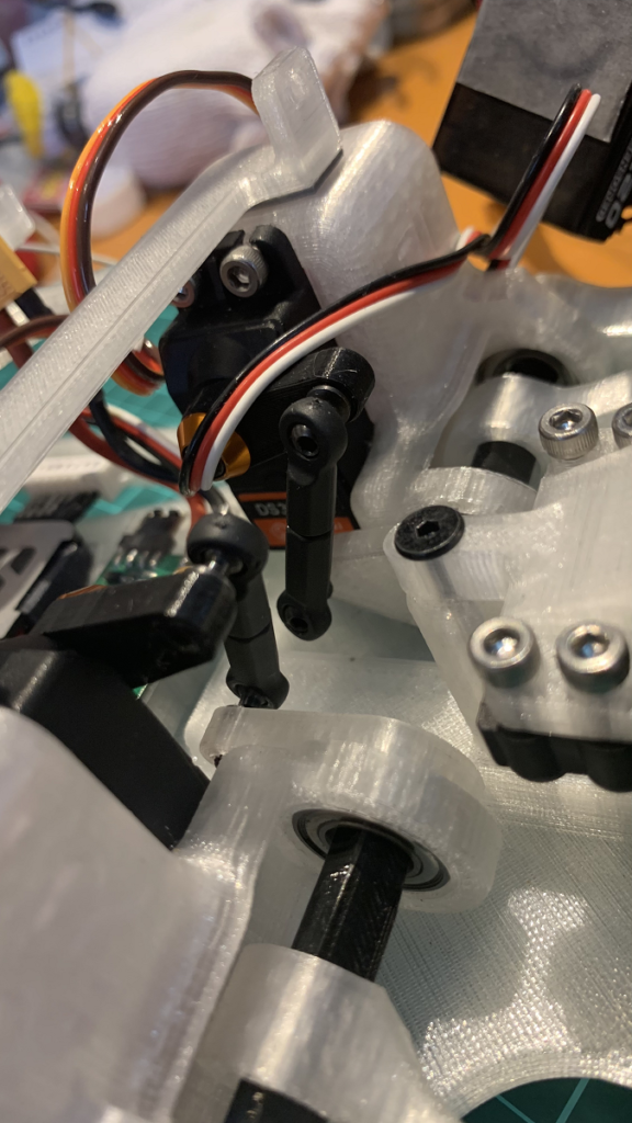
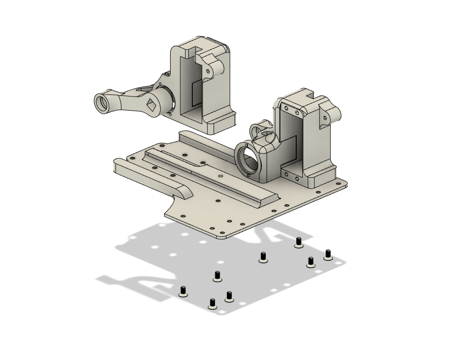
Install 9*17*5 bearings and spring bars as for the front side. The spring lever is different from the front side, so be sure to check that it is springlever_R.stl and that the installation orientation matches the diagram.
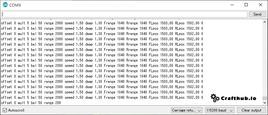
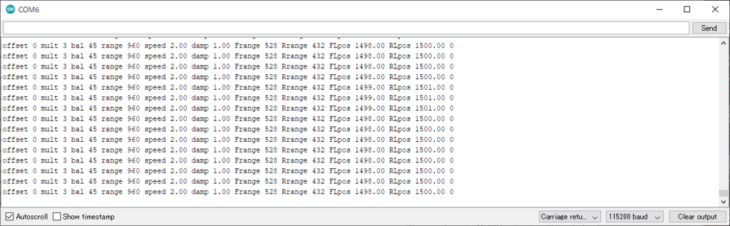
2,Superscale2k20 “ss”unit Unit initialization
First, use arduinoIDE on your PC to connect to SS unit. Make sure you have the latest version of the firmware. The latest version is Ver1.22 (13 Sep 2022).
You can check the version on the serial monitor. Then turn the potentiometer to adjust the offset value to 0, and turn off the power once it is done.
3, Neutral position setting for all servos.
Due to the space limitations of this chassis, it is necessary to connect each servo and SS unit as follows in order to reverse the servo rotation direction.
- SSunitRL output>FrontRight servo
- SSunitRR output>FrontLeft servo
- SSunitFL output >RearRight servo
- SSunitFR output >RearLeft servo
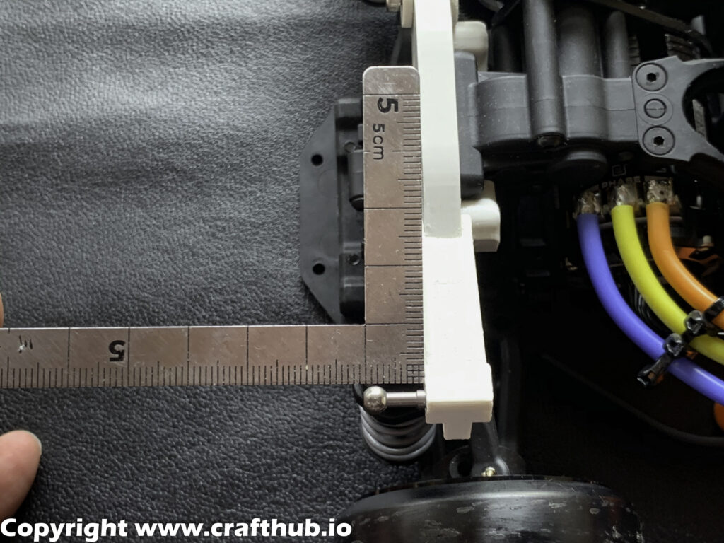
After connecting all servos, place the SSunit on a flat surface, turn on the power, and in a few seconds, all servos are in a neutral position and stable. Turn down the power.
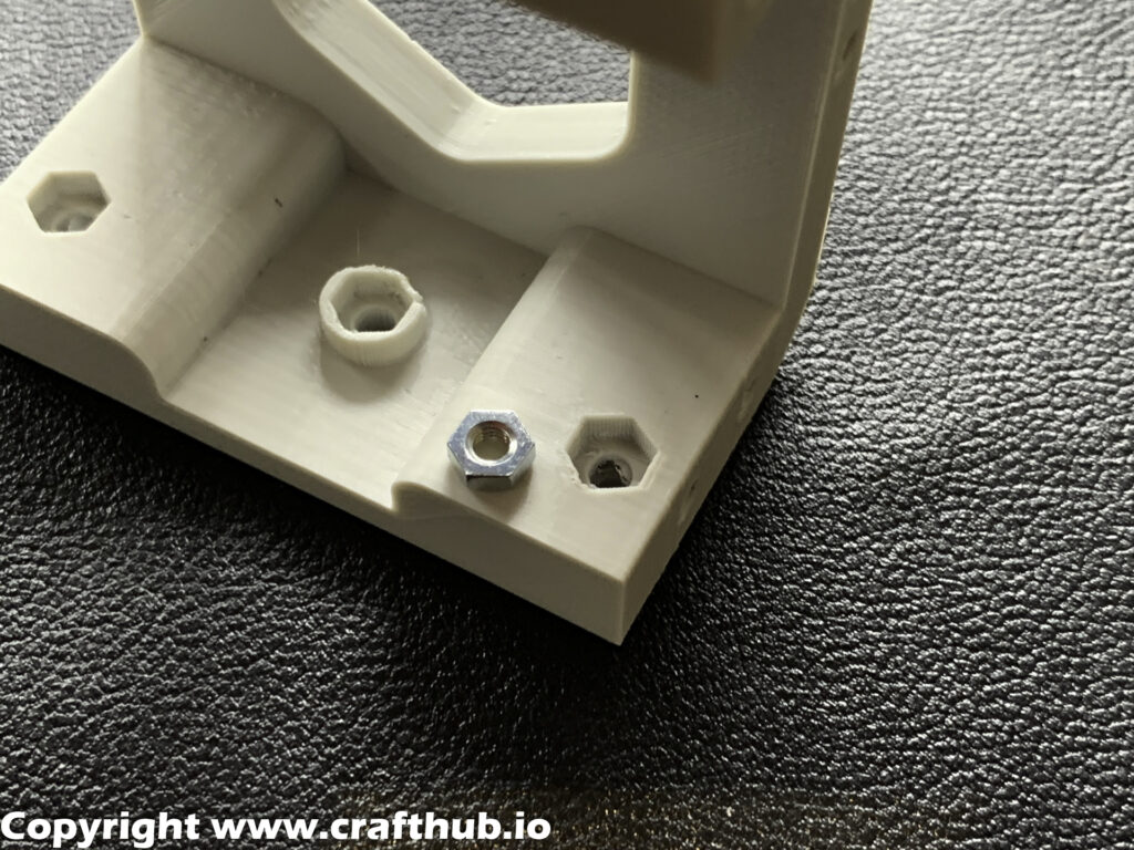
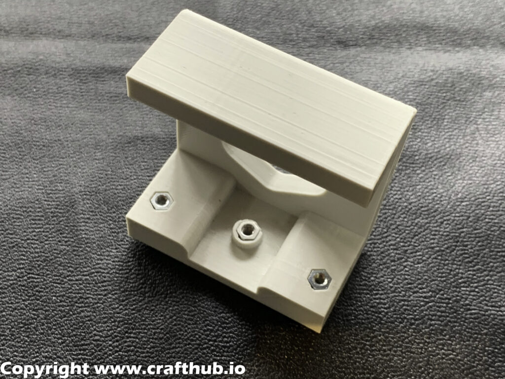
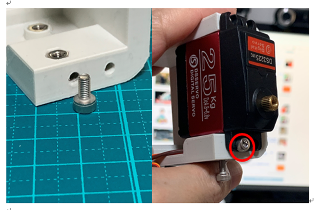
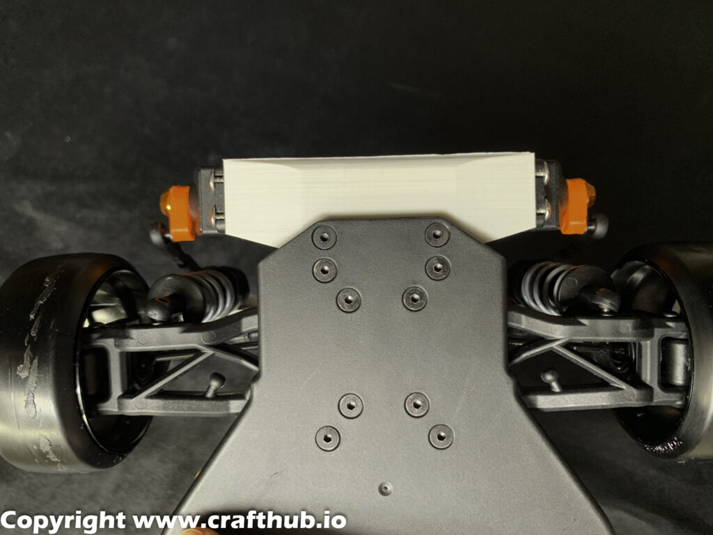
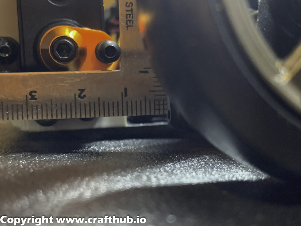
Adjust the neutral position and the axle position with reference to the figure. The servo horn is tightly engaged with the servo output shaft when the screw is tightened.
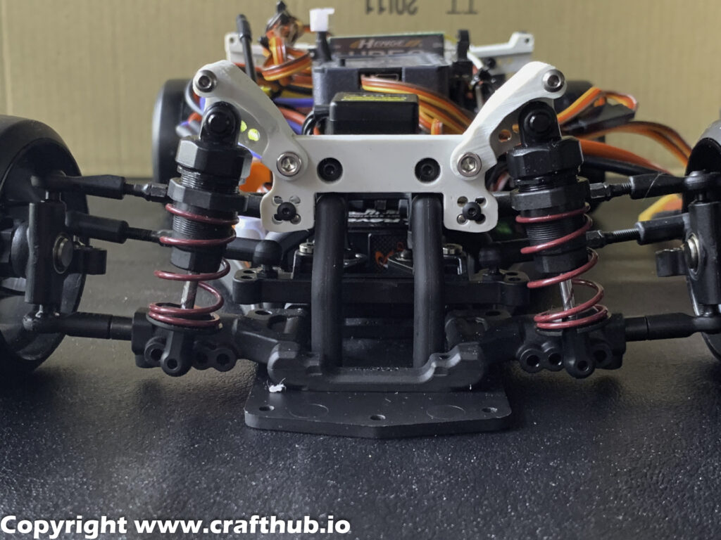
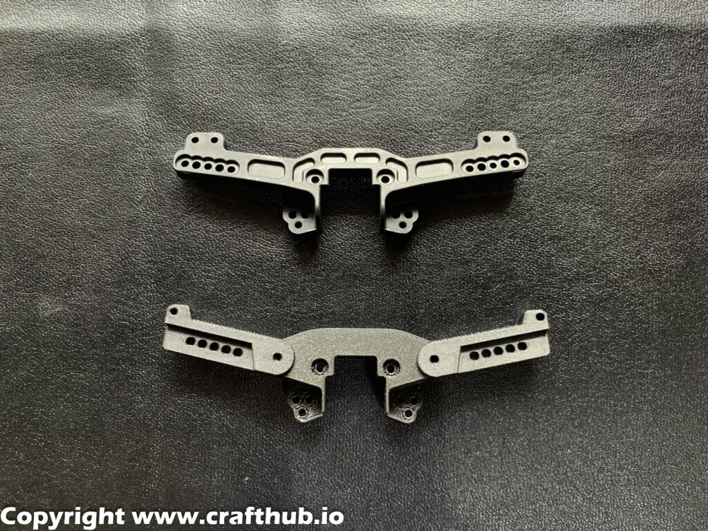
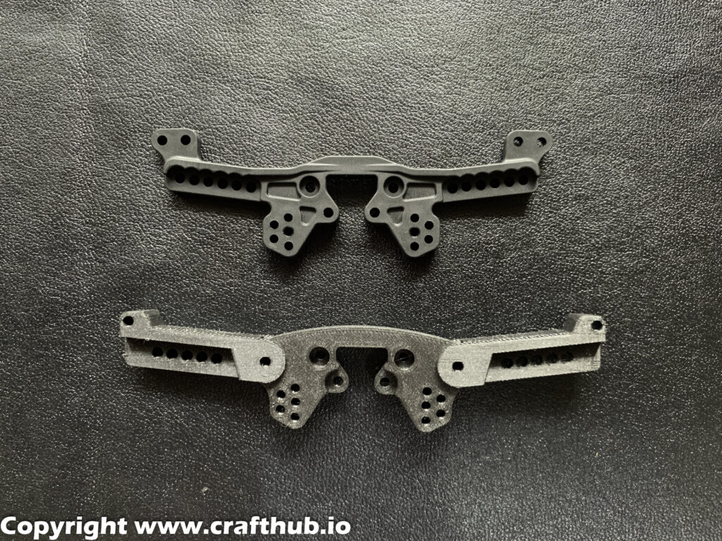
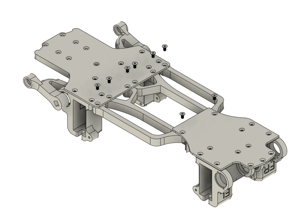
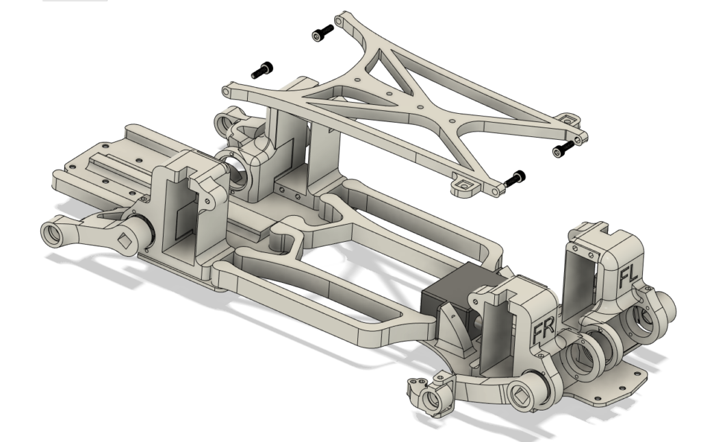
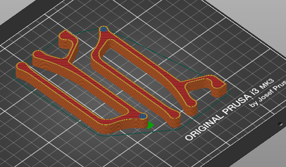
4, Frame Assembly
Then connect the front and rear frames.
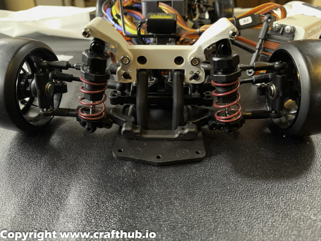
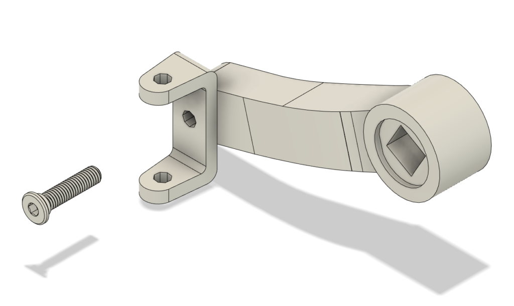
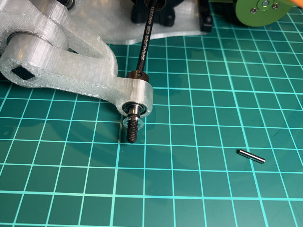
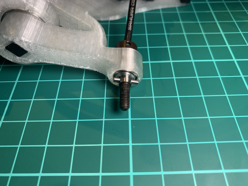
5, Front axle assembly
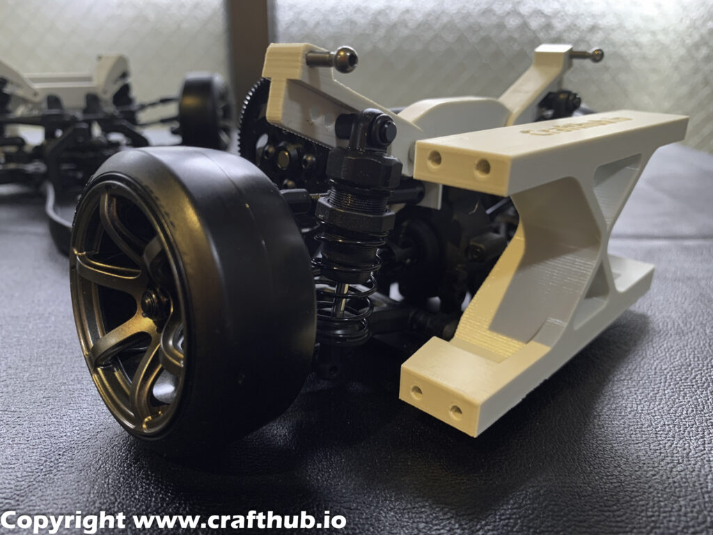
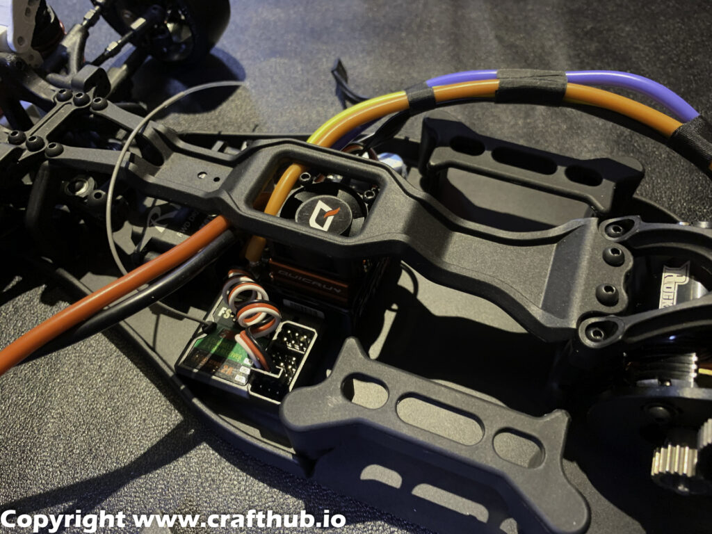
6, Brace installation
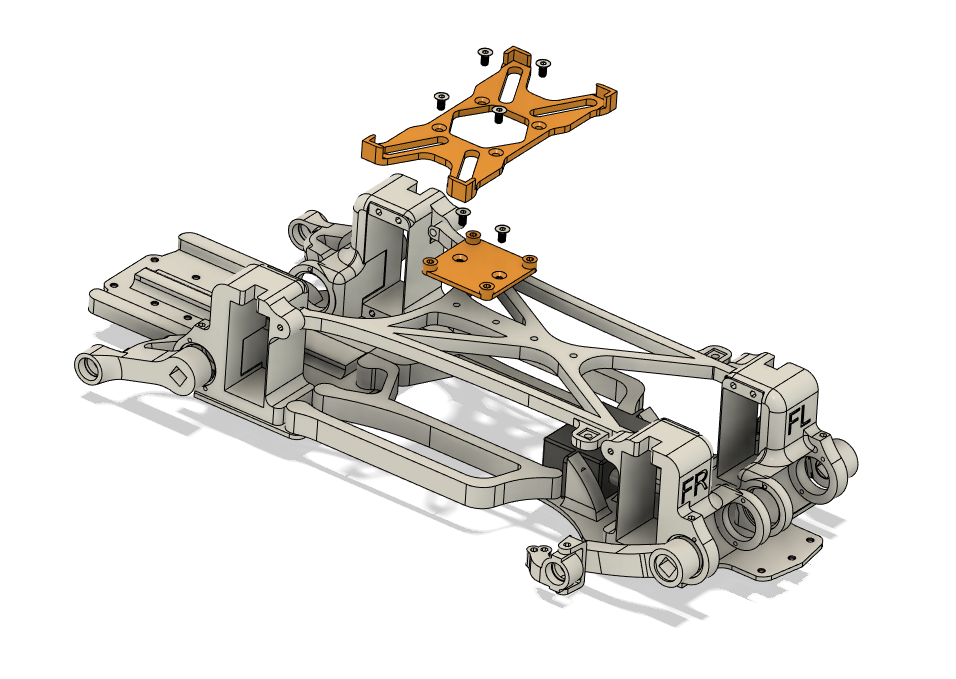
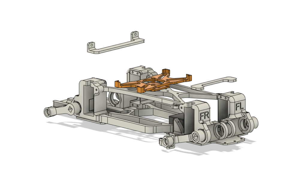
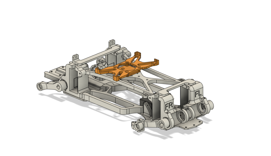
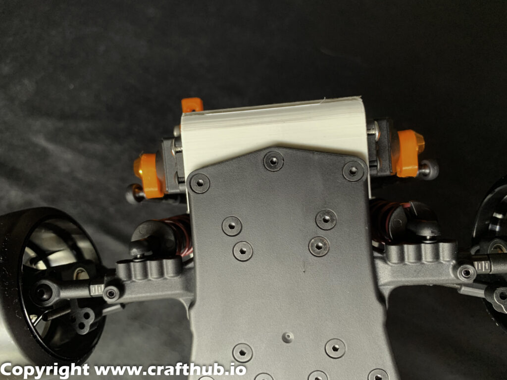
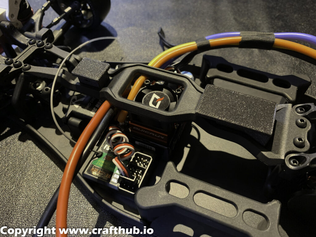
7, Drivetrain
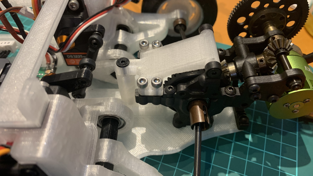
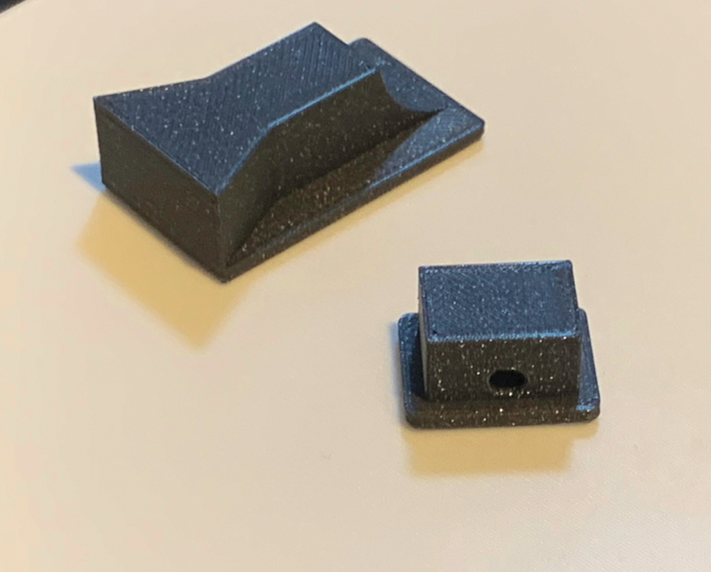
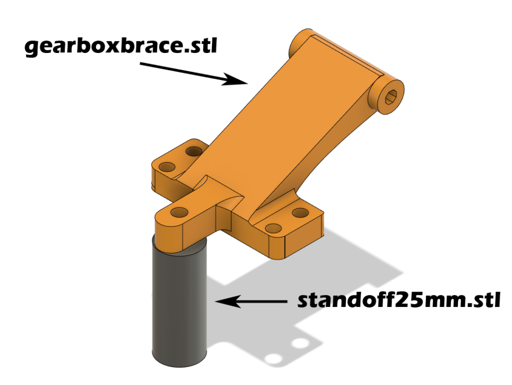
Use standoffs and gearbox braces to ensure frame plate rigidity.
The gearbox brace is also used as an ESC mount.
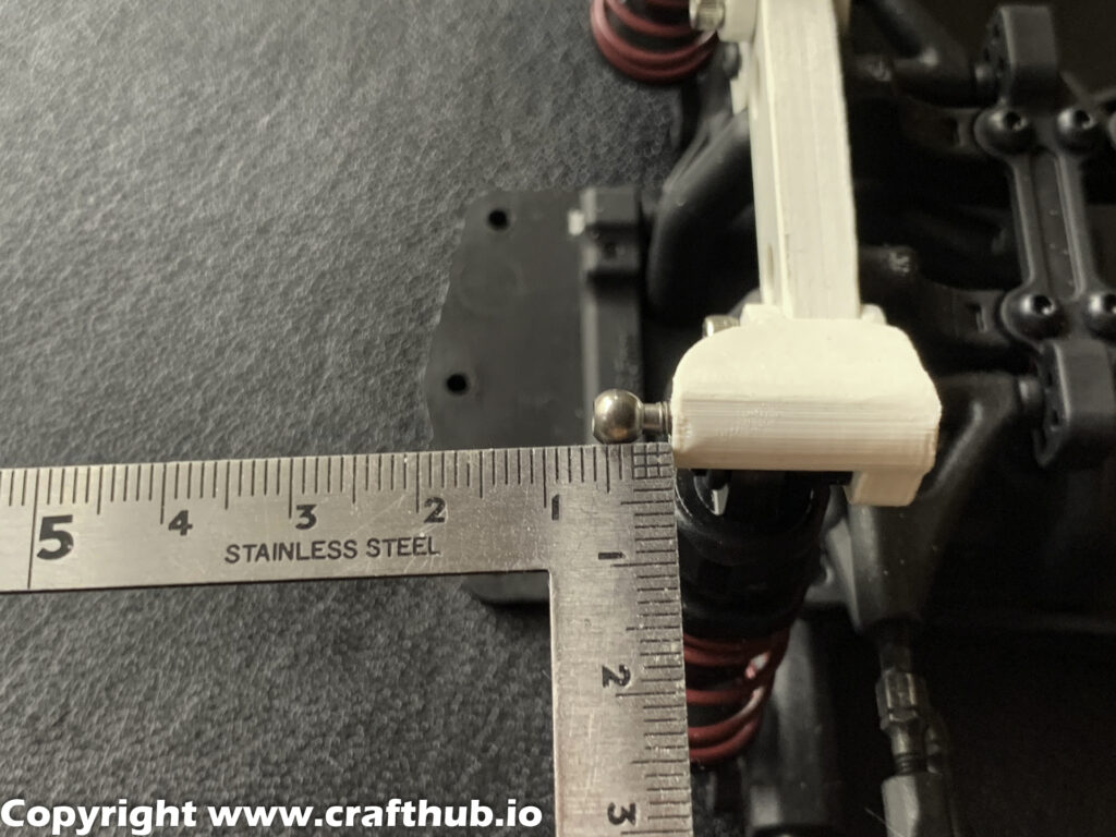
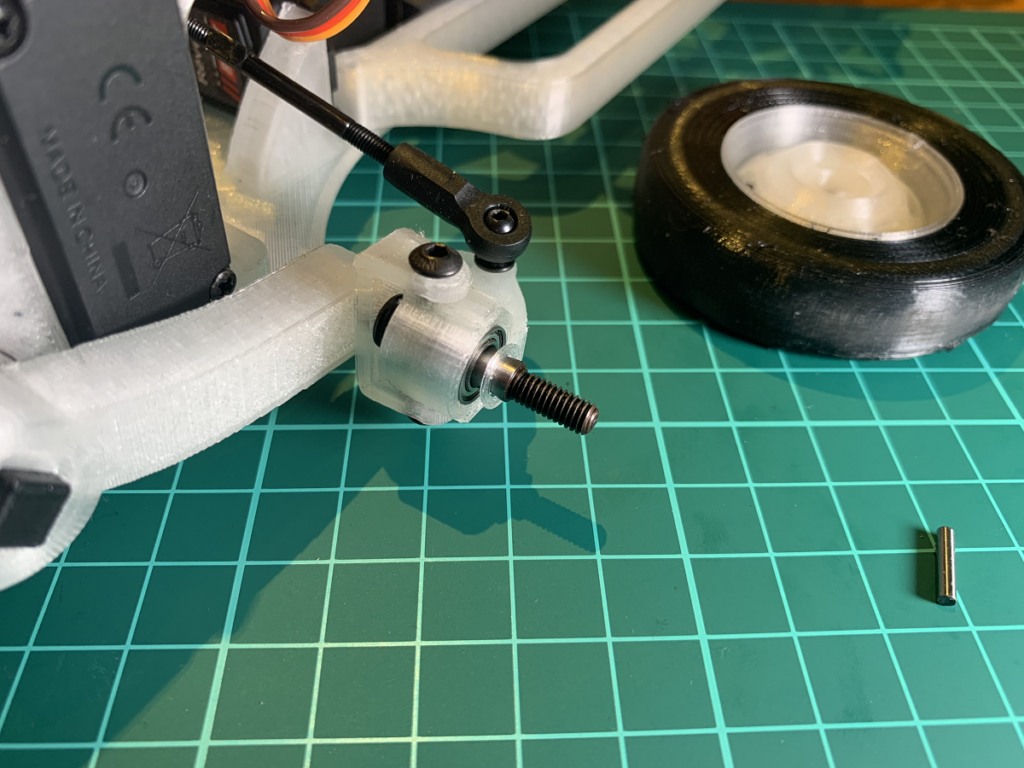
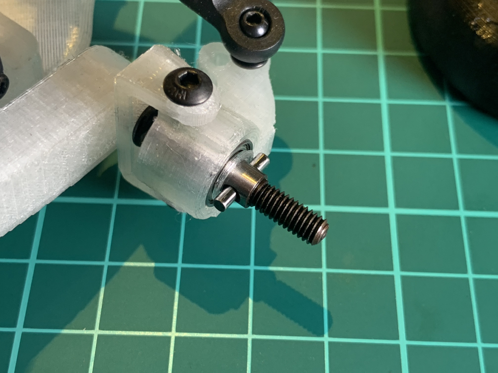
8, Axle with washer
9, SSunit tuning
- offset 0
- multi 3
- Bal 45
- Range960
- Speed 2.0
- Damp1.0
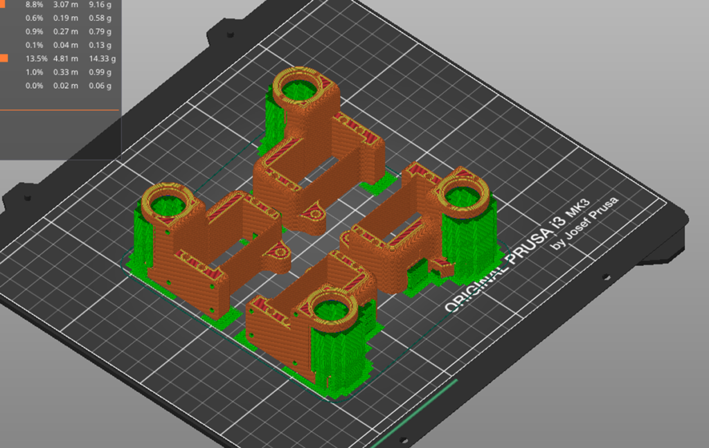
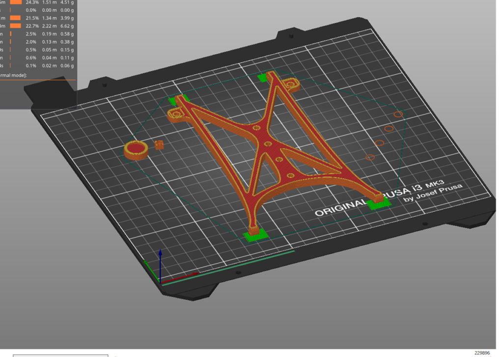
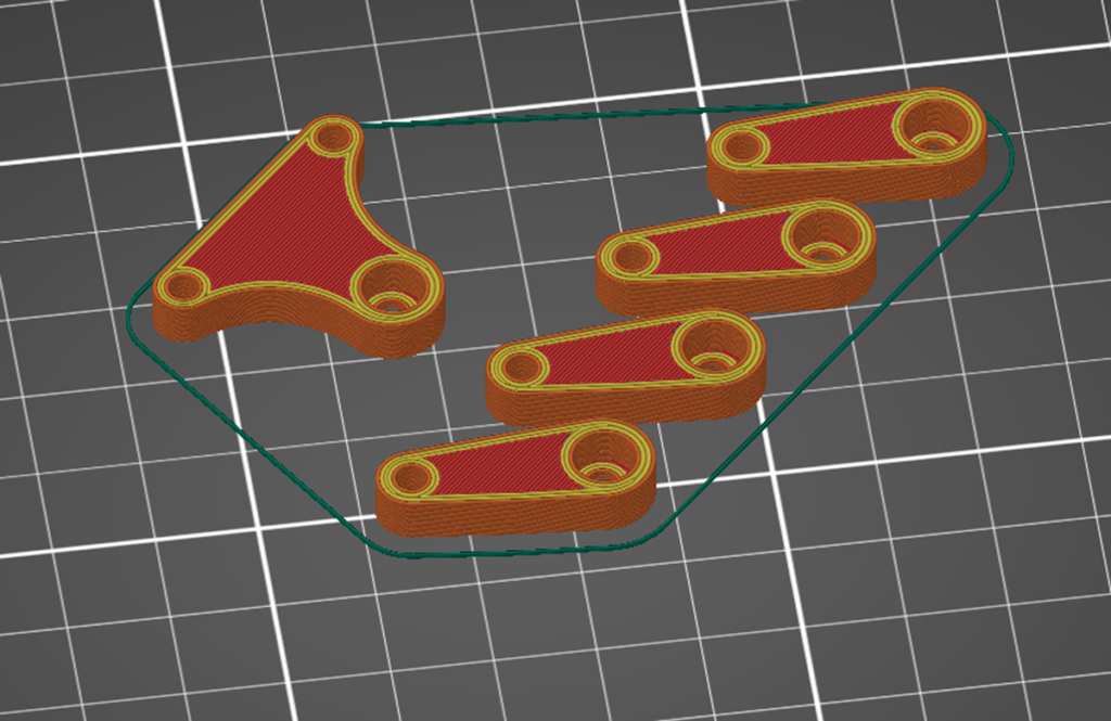
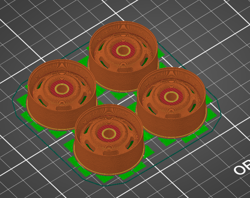
Slice
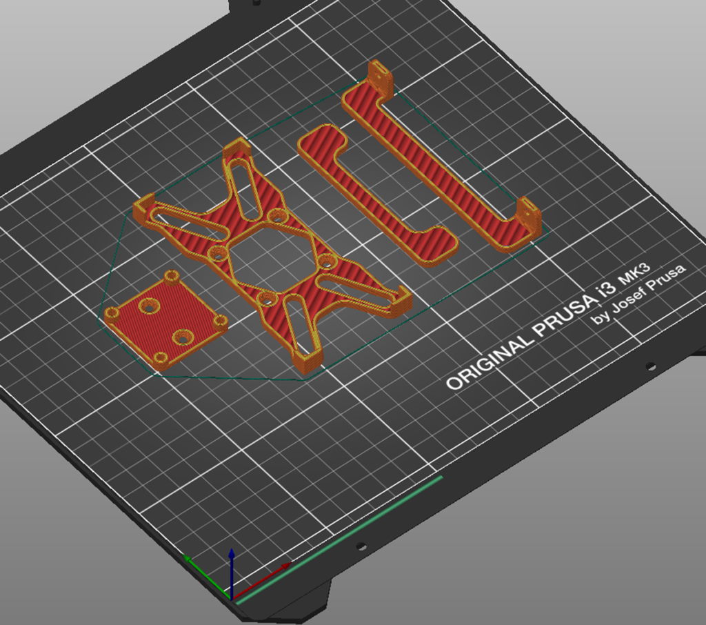
How to get the STL Data
You can Download this model`s Full STL data from crafthub.io